I do have some understanding of the importance of luminance… which is why I take interest in this thread in the first place! I actually have a few of the Black Flat and White Flat 1mm^2 and 2mm^2; and have already done a couple “learning” builds with them (which I still tinker with). I modded my GT Mini with a White Flat 1mm^2 not too long ago; my Uncle liked it so much he’s likely the only guy in the Philippines who has a GT Mini with a White Flat! I thought Enderman’s canon-style layout was great because it gives me a test bed for swapping emitters and optics and electronics. I’ll have to wait however until it gets warm enough outside to get more accurate long-range lux readings without me shaking from the cold.
The recent comments stemmed how to achieve additional luminance to a standard layout reflector-based flashlight in a retrofit scenario - that is, after de-doming (which I haven’t done yet to my XHP70.2). The question was as to how much benefit there’d be if a spherical reflector with a width coinciding with the 30deg. half angle to take the “spill light” and reflect it back onto the die. Enderman estimates about an 11% gain, and how that’s probably not worthwhile. Coming from someone who chases a 1 percent gain to obtain the maximum out of every component just seemed a bit off to me, when other ideas to gain 11% would be far costlier. So I probably defended my position with some half-true assumptions. Still, I think even half, a 5.5% gain, for $3 in parts from the box-‘o’-parts, and a bit of sweat equity from a man that barely watches TV, and otherwise doesn’t have a clue, is not too horrible. Sure I could just buy a precision aspheric lens, get a MarineBeam Illuminator RLT to harvest the Wavien collar (because that’s probably the only way I could get one now) and spend hours like_ pscal_ to make a 3.508Mcd GT. But since I’m trying to stick to the “budget” part of BLF just trying to come up with ways to get more performance on the cheap…
Thanks for the link - it reinforced some notions I intuitively had as well as gave insight on some that were not-so-intuitive…
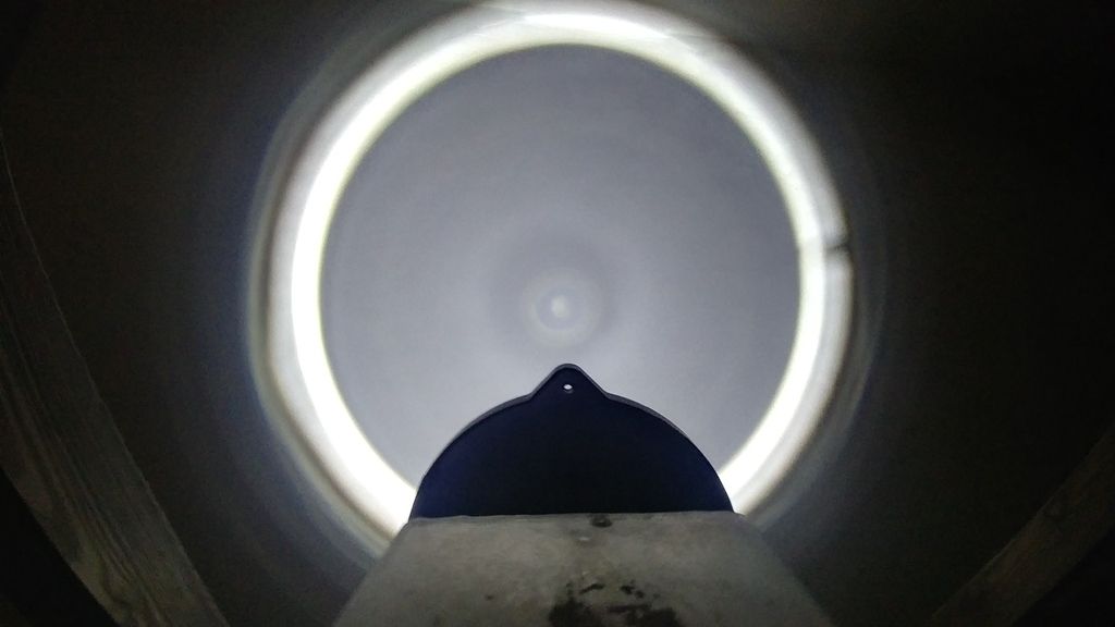
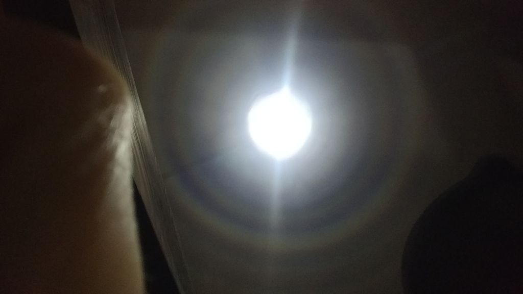
Interesting two lens design (LEDiL Seanna) with an Osram 1mm^2. The first wall shot is with out the exterior Fresnel lens. Not the most practical of lights but it was fun to build. I like to try a center gasket with different thicknesses to see the effect. Maybe removing the first lens and taking a shot. Early stages of this build.
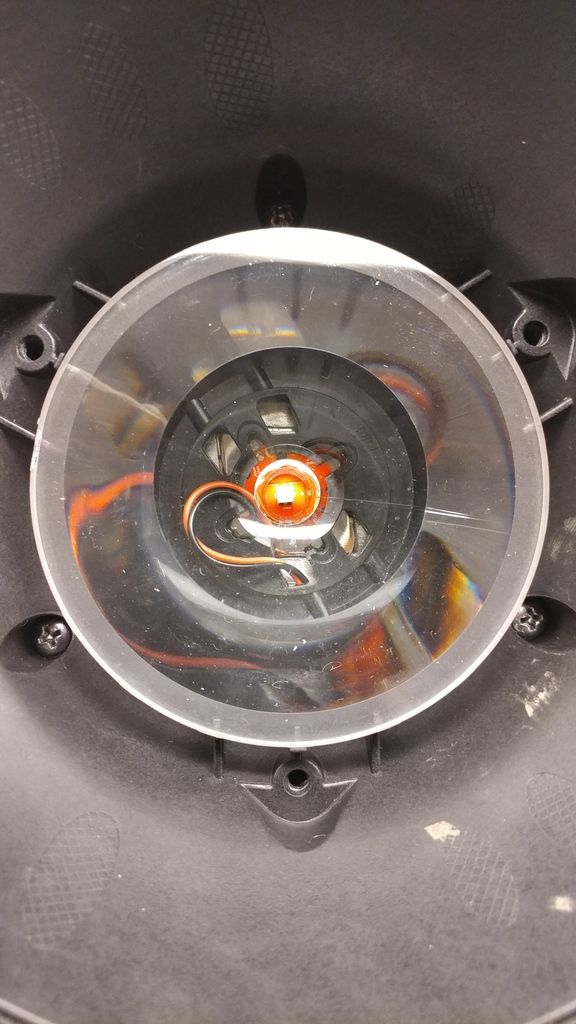
Cool! I have two of these… I fitted one with a 2mm*2, have to take some beam shots. But yes, the interior TIR lens produces a weird beam, like an axicon lens for a laser.
I upgraded my maxtoch shooter 2x with the CSLNM1.TG. I never cared much for the stock dedomed xml2, very green. I had a bit of trouble at first getting the LED onto an XPL MCPCB, then had a LOT of trouble getting the focus, but I finally got it.
So I had time to digest this particular tidbit of info and now it’s bugging me. Because if the intensity remained the same, while the apparent area decreased, then that would be the luminous intensity would increase. But I intuitively guess that’s not the case, so I’m missing something here.
Thanks all for your patience and explanations. I do love reading but most of what I’ve learn has been through experimenting and trial-and-error - meaning I am an LED executioner of sorts. But one never knows the limits unless they’re exceeded…
It’s really easy to overthink it. When you think of the intensity being constant over a given area then it makes more sense that the bigger the area, the more light you will see coming from it.
Yes… I understand that. But, as I mentioned, if the intensity of the surface remained the same, and its apparent area became smaller (because we’re looking at it from an angle), then by the definition above the luminance would increase as you moved further away from center. I figure intuitively that is not the case, but I could may well be mistaken. I don’t think it’s overthinking things; We could easily take a lux meter and orbit 180 degrees around an LED and know. But we don’t need to - the manufacturers provide us that data. So something’s amiss in the explanation; either there’s a correction factor based on an angle from the axis of the LED, or something.
I guess we’re thinking of “intensity” differently then. I think of intensity as a constant, like one unit of brightness. More units take up more space. So, if you have less space, you have less brightness. To get more brightness from the same space (or from less space), you have to increase the intensity itself. Like a building has a specific size footprint. You can get more space by adding more buildings, but you need more land to do that. If your land is limited, the only way to get more space is to make the building taller.
I think there might be some wording confusion. In my quote above, when I said “intensity goes down as you go to the side of the LED” I meant go down in angle, as the angular distribution graph in the datasheet shows.
That graph shows the luminous intensity (cd) as a function of angle. It basically is a graph of the apparent area as a function of angle. The apparent area goes like cos(theta) which is the approximate shape of the graph. The luminance of LED (cd/mm^2) is a constant. Right above the LED (zero degrees) you have the full die area, say 2mm^2, then at an angle of say 60 degrees you have an apparent area of half that, 1mm^2 which gives you half the intensity.
Yes, I understand that too. I was referring to the definition given to me above, that luminous intensity is the product of the surface area and candela. But since the apparent LES will reduce with increased viewing angle from center, then a) if the luminous intensity is constant, and the apparent surface area is reduced, that means the candela increases with the angle, which doesn’t make sense, or b) the luminous intensity decreases as one moves away from the center; because if the candela remained constant, and the surface area became smaller, that has to be. In other words, the intensity of the LED light at a certain angle is directly proportional to that angle it’s being viewed from in relation to head-on. And the reason I bring this up is because I’m trying to understand exactly how_ much_ of the total output of an LED goes into a typical parabolic reflector (using a GT/GT70 as an example), and how much goes into spill. And I postulate that the light that goes into the spill is actually more intense as a percentage than described to me in relation to the light reflected.
That’s what I’m saying all along. If the luminous intensity from 60 degrees to 90 degrees drops off a cliff, then how does 66% of the beam half-angle contain 75% of the lumens as claimed above?
Luminance is cd/mm^2 (well technically it is per m^2 but we mostly deal with small LEDs here) Intensity is cd
The luminance of the LED stays the same, but when you look at the LED from off-axis the area is smaller and therefore the intensity (cd) is smaller because luminance * smaller area = less intensity.
That is why a lux meter at 90 degrees from an LED will show low lux even though the LED’s luminance (cd/mm^2) is constant.
Oh, that is another geometric effect. The intensity vs angle graph in the datasheet is not the correct graph to integrate in order to get the total lumens. You have to also integrate as you rotate around the axis normal to the LED surface. Think about how all the light from an LED fills a half hemisphere. There is a lot more area and light at around 45 degrees compared to close to 0 degrees even though it is less intense. See here for discussion and a graph of the resulting light output vs angle.