Lookin good gchart
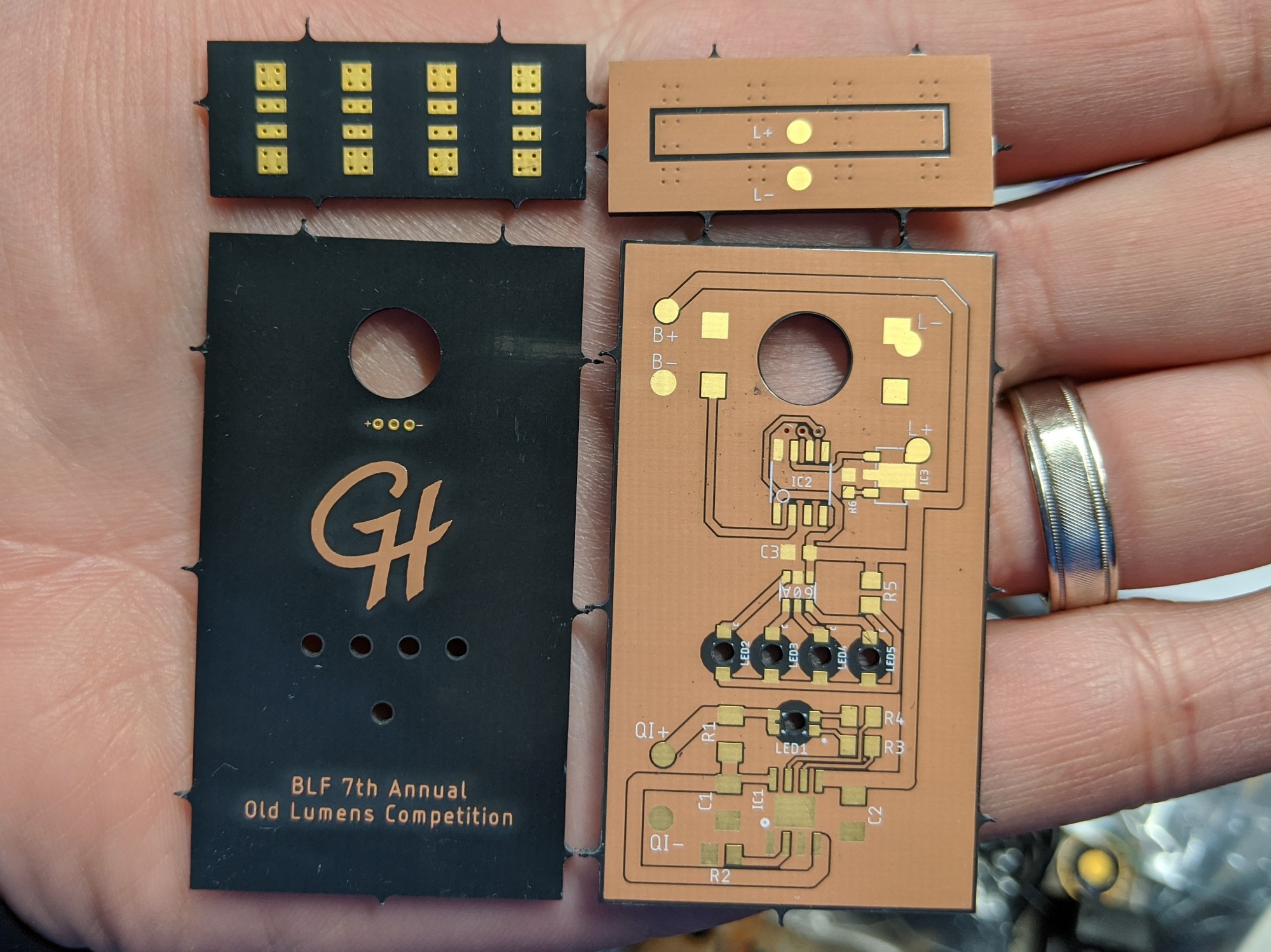
Among other things (see the OP), PCBs have been created and ordered using Oshpark’s After Dark service (black substrate with clear mask).


After dark for black magic?
They look good. ![]()
Black Magic, you know it!
I recently tried the After Dark for some tailcaps and they came out great. To take full advantage of the service, you need to tailor your design for it so that the traces look good (and potentially using copper for labels instead of silkscreen):
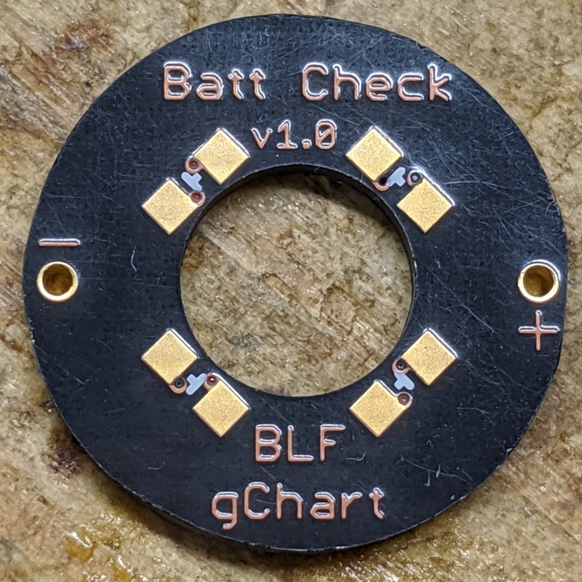
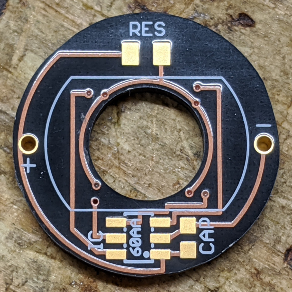
![]()
I’m somewhat jealous of your electronics skills ![]()
And I of your metal work skills! Your creations are inspiring.
PCBs arrived today and they look great! I can’t wait to get them soldered up and tested.
Wow. Looking real good. It really is 50% black magic now. ![]()
Haha, I see what you did there, Moose. ![]()
Only 3 flashling pins? Are you going to use TinyAVR? ![]()
Yup! It’ll use an attiny412 running RampingIOS (D4 V2 UI). I originally hoped for getting Anduril on it, but I don’t think I’ll have time before the end of the contest to port Anduril over to the TinyAVR 1-series. Maybe afterwards… that’s what exposed pads are for, right?
![]()
I’m sure you just cast a spell then…. :laughing: Looking forward to the next update ![]()
Multi talented guy here fellas. Someone into black magic and can speak fluently in, not sure which, either Chinese or Swahili.
We are lucky to have you around gchart. love your work. ![]()
wait, you will use 3d printed parts in final product?? i just noticed that, actually it was your build that inspired me to enter with a 3d printed light. just like your holders inspired me to learn graphic design. looking forward to see finished build,
Nope, no 3D printed parts in the build. That was merely a mock up to demonstrate what I’m shooting for… And to practice my 3D design skills.
Actually only 2 pins are needed for flashing if the light is running on battery power. The + from the flashing unit is only to power the MCU, if it already has power from a battery it’s not needed. All that is required then is common GND with GND pin and the UDPI programming pin.
I think it’s funny that only just now someone questioned the 3d printing despite this being in the handmade category :laughing: myself included, I didn’t realise till now :person_facepalming:
But as you pointed out that is just a mock up. Looking forward to the actual build ![]()
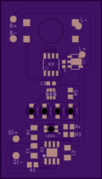
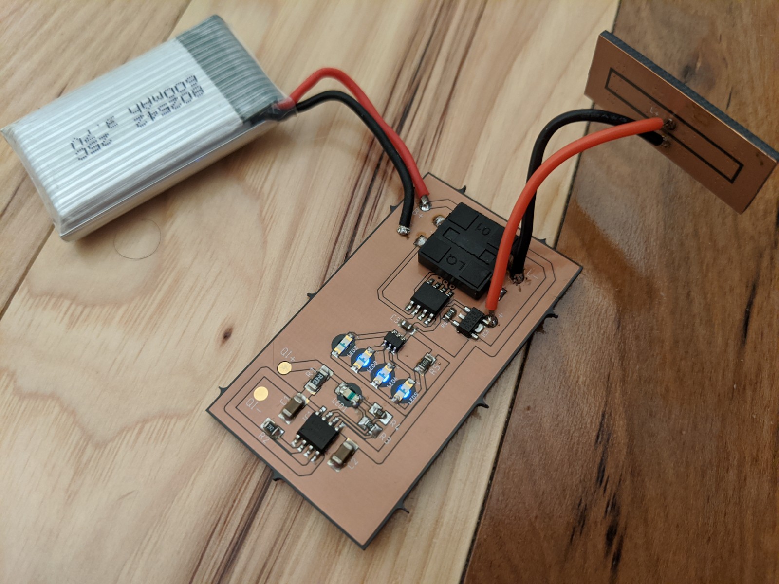
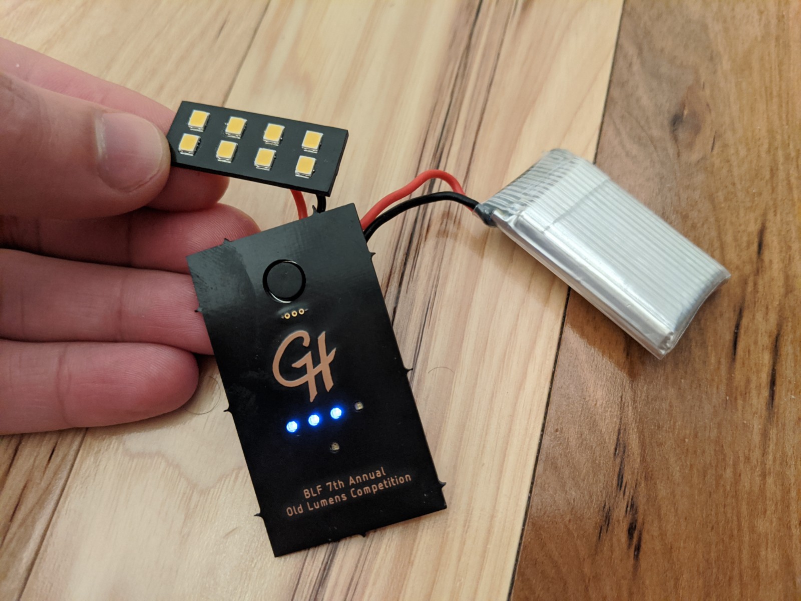
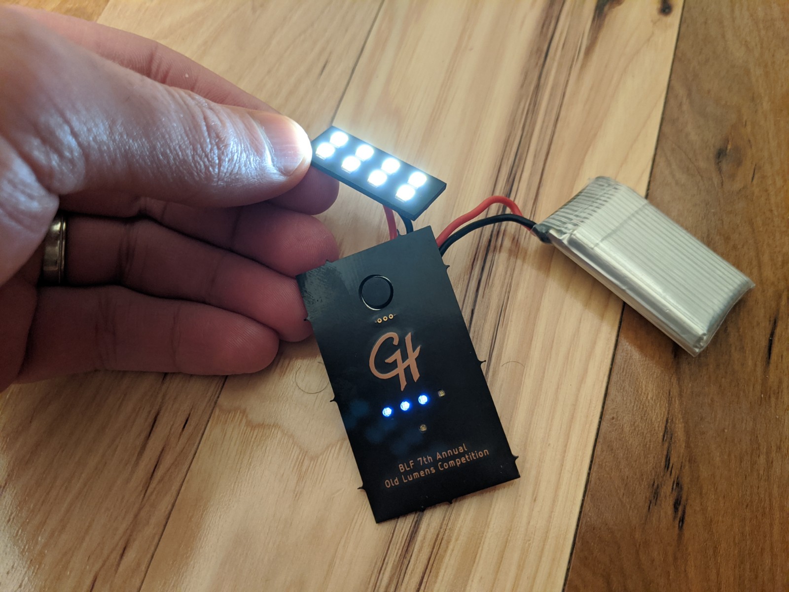
Most of the electronics have been assembled and tested for functionality. The main PCB has been assembled, along with the LEDs on their PCB. Sidenote, but the 4000K looks really good; I’m glad I went with those. I soldered the battery on (at least temporarily). The piece I haven’t soldered on yet is the Qi charging coil, thus the charging circuit hasn’t been tested yet either. Perhaps tonight.
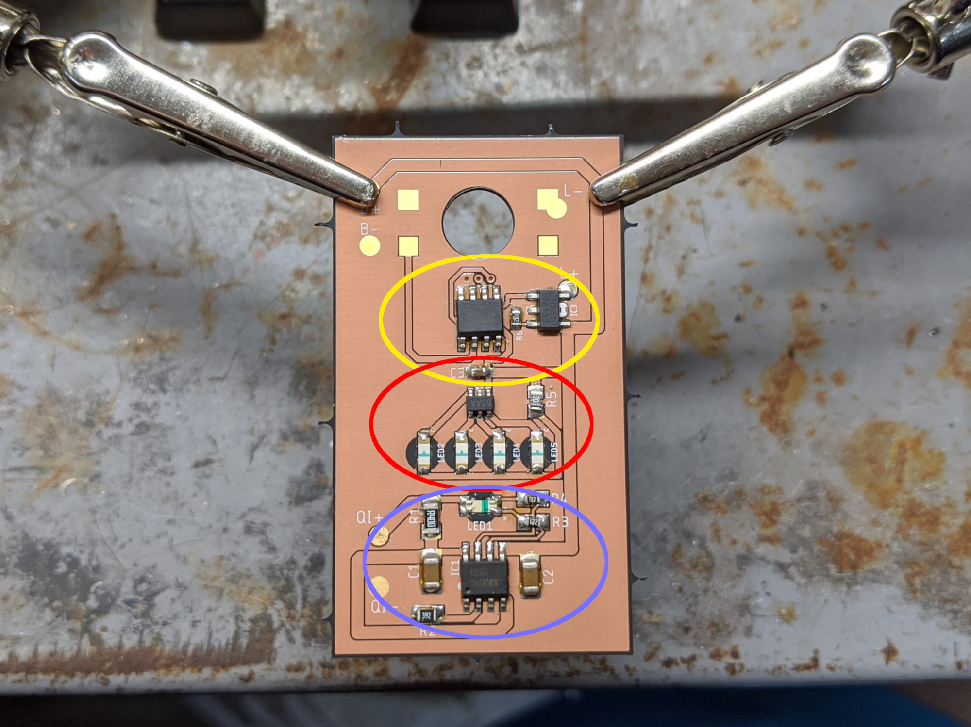
Here’s a breakdown of the circuitry (encircled in the image below):
- Charging circuit in blue: these parts were scavenged off of a standard TP4056 Micro USB charging module. The modifications here are (1) the input will come from the Qi receiver instead of the USB port, (2) the current set resistor was swapped so that the charge current will only be 300mA instead of 1A, and (3) the indicator LEDs were replaced with a single reverse-mount red/blue LED.
- Battery indicator circuit in red: this is the same HM1160 circuit used in my recent LED tailcaps. This is a really easy-to-use IC with minimal part count. I used blue reverse-mount LEDs for this.
- Main control circuit in yellow: the brains are an ATtiny412 running RampingIOS (D4 V2 UI) which are controlling a CN5710 which is set for 1 amp. The UI is currently stock, but now that I know that everything is working fine, I’ll be doing some customizations like re-arranging the multi-click options and implementing a “hold for low while in lockout” feature using the exposed programming pads.
Next up: (1) test the Qi charging circuit, (2) form the brass casing