Well, I have gotten a little bit done on this light and decided to post the changes as I go, here in this post. Kind of a before and after.
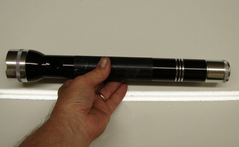
Here's a shot of the light after filing rings and doing a little polishing here and there.
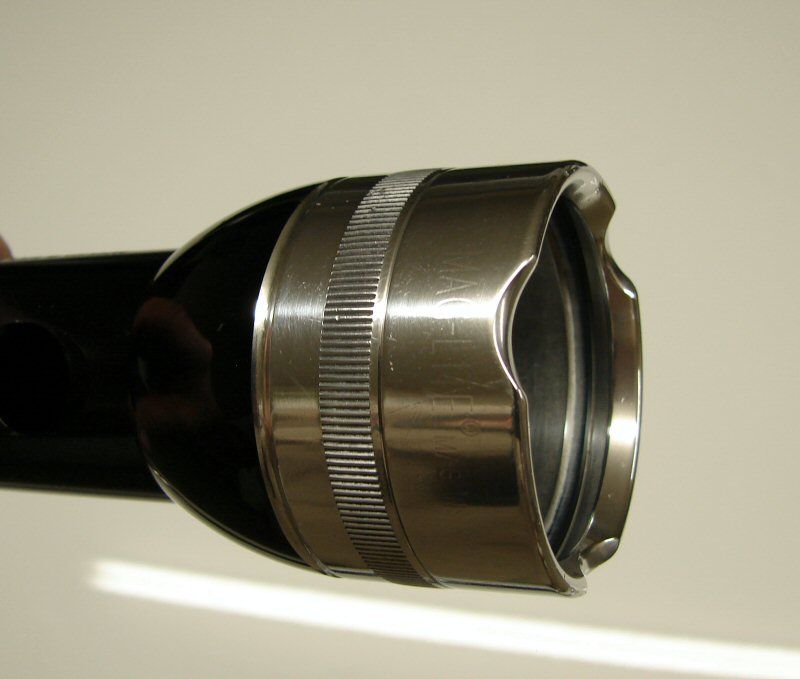
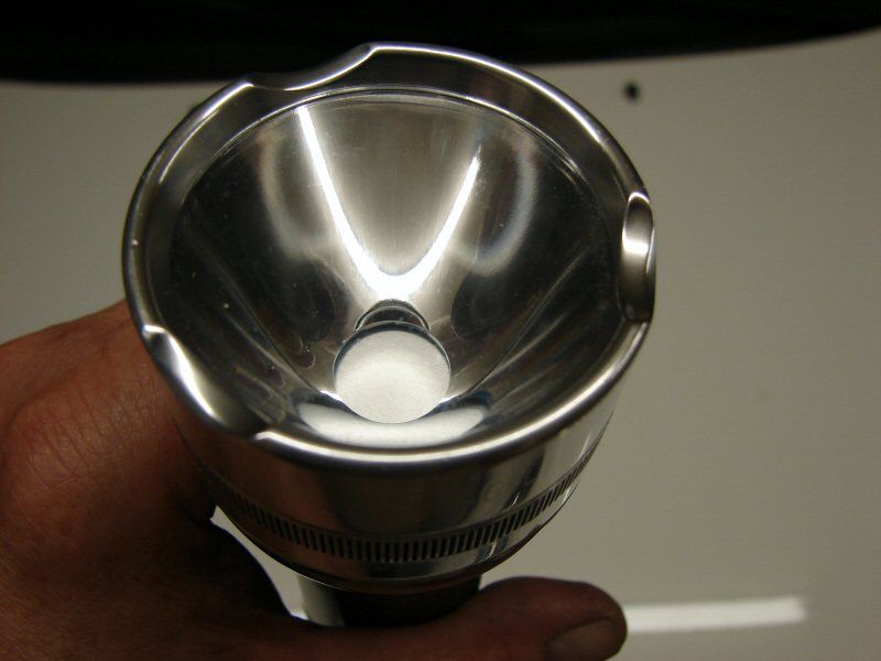
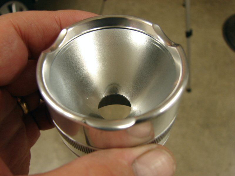
Here's a closer shot of the head. I went with just three crenelations on the bezel.
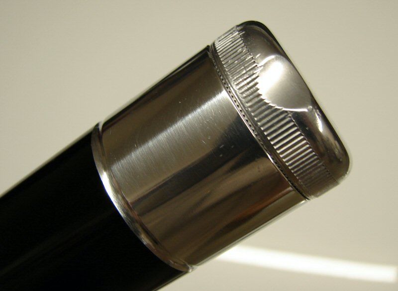
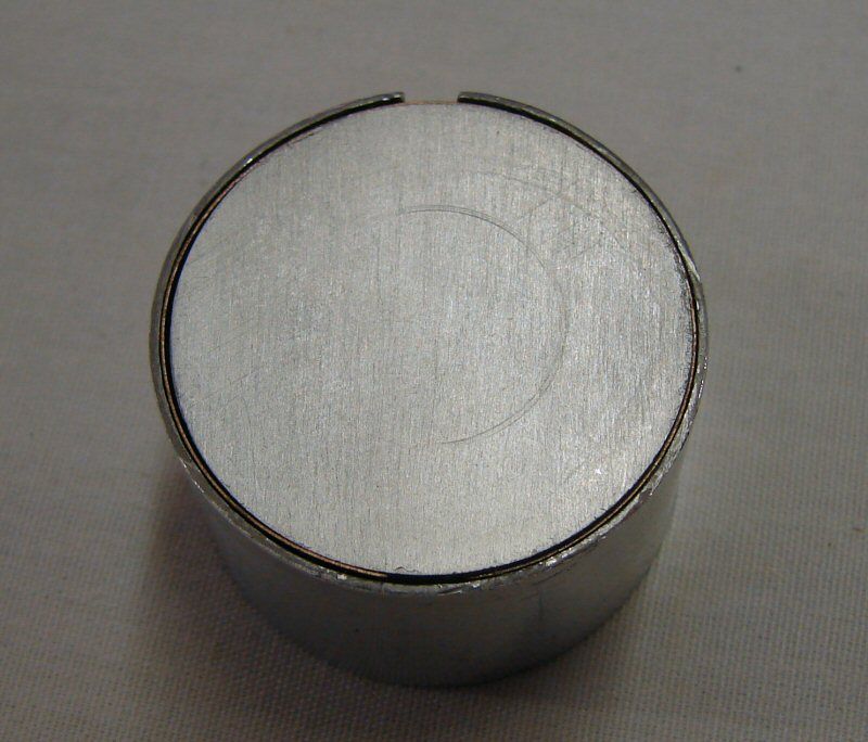
Here's the tail section. I also did just 3 crenelations on the tail cap.
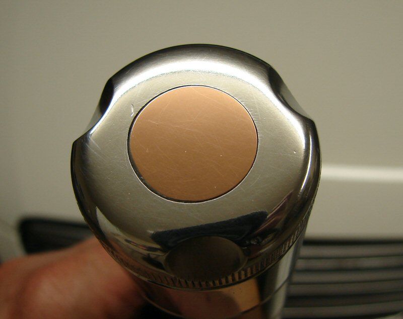
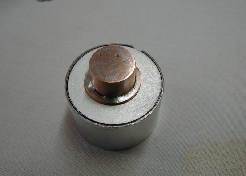
Here's the copper insert in the tail cap. It's not fantastic, but I think it looks nice and it's different.
In all these photos, you will notice dings, scratches and other marks. I said before I wasn't going to take out all of the signs that showed this was a work light and I didn't. Also, when I say polished, it would be better to say shiny, since I don't really polish. I consider that polished means no marks and a mirror finish, but I don't do that, I just make it shiny. I just tend to abuse the word polished.
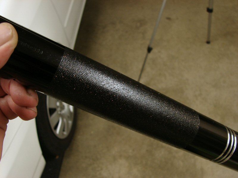
I have done nothing with the knurled area yet, but it will probably just be painted. I have thought about paracord for a couple days and have decided against it. I just don't care for paracord wraps. All the lights I have seen with it on them just look odd to me.
That's all for now 7-12-12
-------------------------------------------------------------------------------------------------------
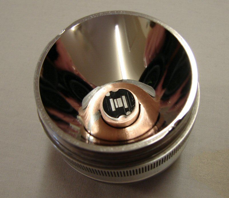
Not much got done tonight. I did work on the switch and heat sink.
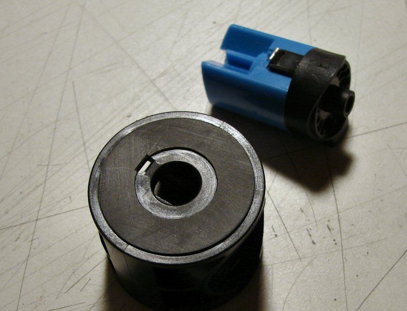
I decided to go with a new switch. I have a couple lying around, from when I do tail cap switches and I save the stock ones. I removed the tower here.
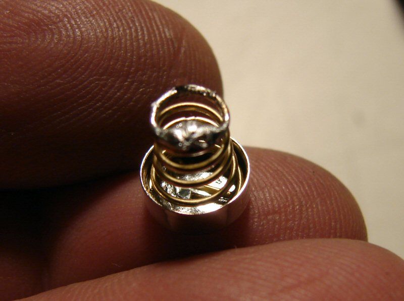
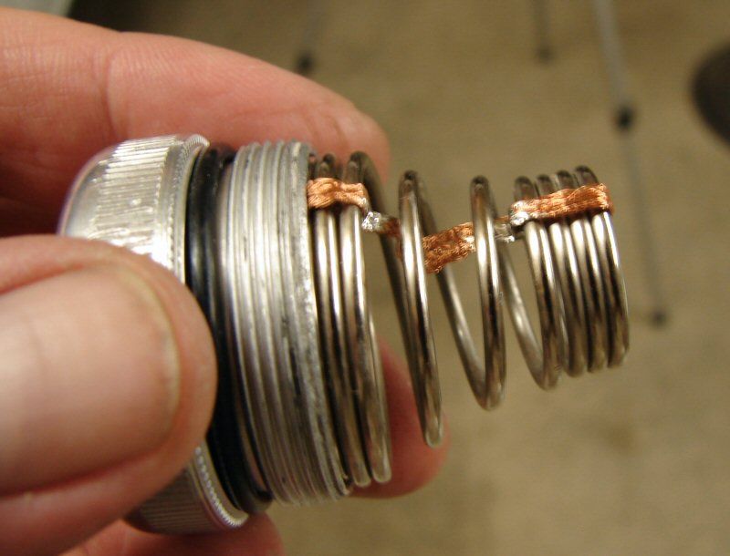
This is the positive cap that fits in the switch. I have soldered a gold plated spring in it. I will explain in the next shot.
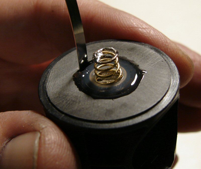
I decided that I was tired of poor grounds and tired of a lot of wires, so I have decided to solder the driver to the spring. That way there's no wire, it'd direct. I will also use stock negative contact and when the driver is in place, I can cut the negative contact to length and bend it, so that I can solder it directly to the negative outer ring of the driver. That way I only have two wires for the LED and I will be using the stock ground.
I also started fitting the heat sink into the body.
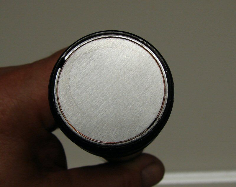
There's more to do, but it will fit tight in the body and I will use a hidden screw through the body, into the heat sink when the actual position is determined.
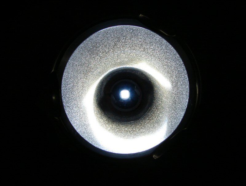
I am going to play around with the stock reflector. I want to see how bad it will do, especially if I use Krylon on it. Time will tell. I also have a Maglite LED reflector and an Aluminum reflector if all else fails. With only 1.7A on high, the stock reflector isn't going to melt and I just want to see what I can do with it. I cut the cam off of it here.
I will put a glass lens in, but I will also polish the stock one and send it along too.
That's all for Friday the 13th.
-------------------------------------------------------------------------------------------------------------------
Saturday the 14th.
Here's a shot of the heat sink. Nothing special. I have 1-1/4" rod stock still, so I'm using it and making sleeves to fill the gap. When this one is in place, it's tight and it will have a screw put in, to hold it in the body.
Then I got to thinking... As I already said, I want to play with the stock incan reflector, but I really want to be able to adjust the depth, by screwing the head up or down, to see what it will do with the beam. So... I decided to throw together a small pedestal.
Now, that's not the star I will probably use, but it was lying around and I could see what it looked like.
The copper pedestal is a 3/4" diameter copper round, with a 3/8" copper coupling on top and some of this inside,
plus some solder, to tie it all together.
I think it will work for what I want to do, which is see how that stock reflector does, as I turn the head up and down.
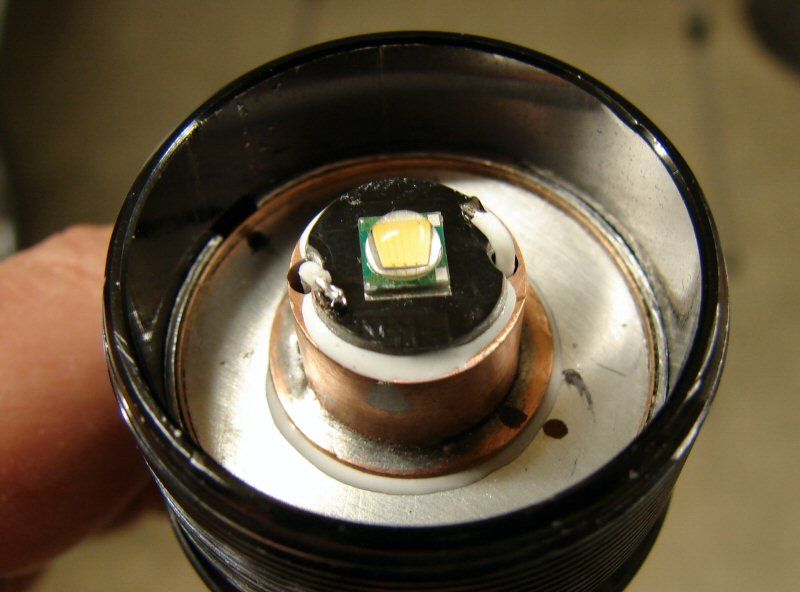
I got the T5 emitter today, but it's on a 20mm star, so I will have to reflow it onto a 16mm star, that has been cut down to 14mm, so it fits the pedestal.
That's it for the week-end. The driver comes in next week and all of this will be buttoned up so we can see what it does.
----------------------------------------------------------------------------------
Finishing up with Maggie;
I received the driver from E1320 (Thank You), He used a 4X7135 driver and added one chip, so it would be around 1.7A but what impressed me the most was the detail. He put a spot of solder on both of the led solder points and also on the positive and negative on the underside of the board! Impressed with that!
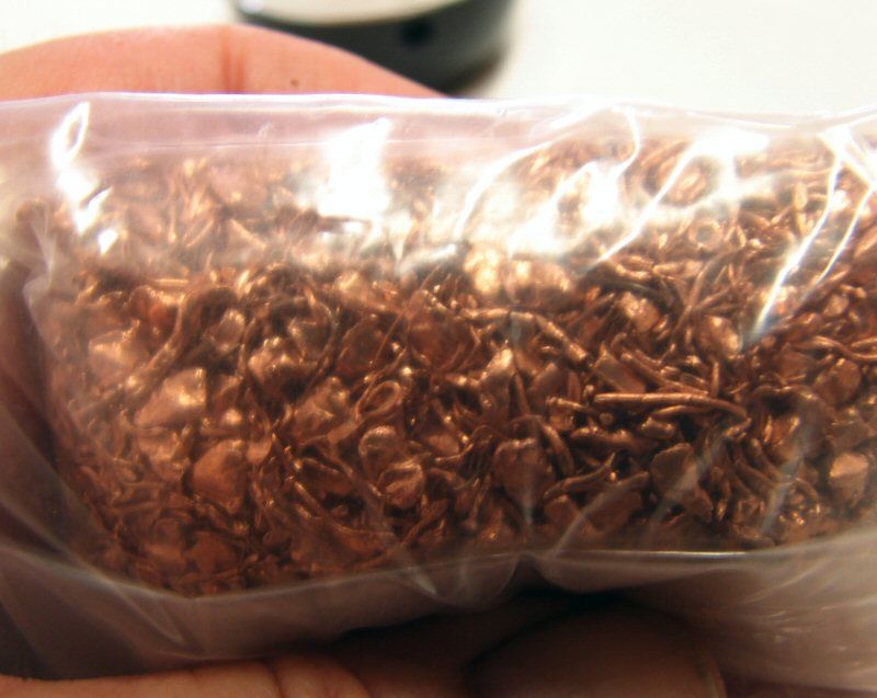
Unfortunately I don't have a photo. I took the body to work last night and painted the knurled area with the Rustoleum Textured paint I have used before. It's the black, with copper flakes. I figured it would go well with the copper insert in the end cap.
When I got home from work last night, I decided to finish the light. I soldered the driver positive, to the spring on the switch and soldered a wire from the cut off negative terminal of the switch, to the negative ring on the driver. Then I soldered two wires to + & - on the driver, to go up to the led. I used solid wire for the led wires. I am liking solid wire a lot more lately. As long as it's not where it will flex a lot, it's better than stranded, in my book. Easier to form, easier to solder and it should carry current with less resistance.
Anyhow, I put the switch in, with the led wires sticking out and slid the heat sink down, threading the wires thru it, while pressing it in place. Then I just snipped and soldered the led wires and it's done.
It works! That's low mode.
I ended up doing the pedestal for the led, just to see what I would find, when moving the stock reflector up and down. It's just as I expected and just like I have seen with every reflector, when using a led. There is one spot where the reflector gives you a perfect beam and anywhere else in the up/down range, there's an imperfect beam, that I just don't care for. LEDs are not like incan bulbs. Focusing does not work. You get either a perfectly focused beam, or nothing. I also sprayed the reflector with Krylon. I don't like artifacts. I have learned that I can use a stock incan reflector, but I just am not impressed with it, so I will be going back to aluminum reflectors from CNQG.
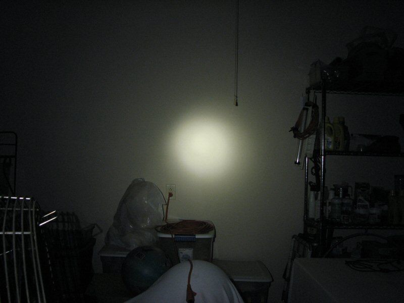
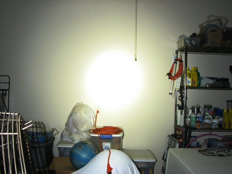
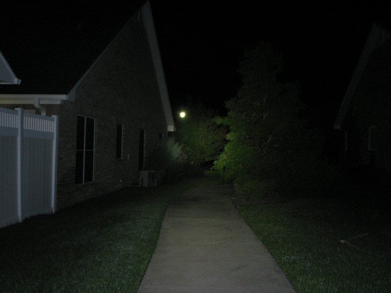
So... the light is done and it's time to show those beam shots. I use a Canon S3IS and it was set to Manual, IOS200, Shutter 0.5 seconds, Aperture 2.7, White balance set to daylight. I had it on a tripod.
The first shots are inside the garage against a dirty tan/yellow wall. There are five modes to this driver, but I only managed four of them with the inside shots.
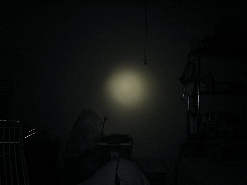
Looks about like what I saw
Looks about like what I saw
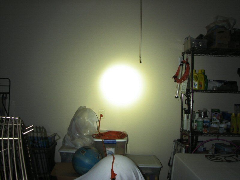
Looks brighter than what I saw
Looks much brighter than what I saw. See, here's the thing, cameras don't capture what the human eye sees, because the human eye will automatically adjust brightness, by opening and closing the iris. What the camera saw is with the shutter speed and aperture the same through all the shots. What I saw is because my iris opened and closed to adjust for the light, to help it see better on low and help it to see less on high. That is the problem with all of these beam shots. Keeping a standard setting, may very well show the amount of light that is there, but that is not the amount of light your eyes "perceive", because your eyes adjust to cut down the light, on purpose, to protect themselves, so you never see the actual amount of light! Don't contradict, I am right. LOL
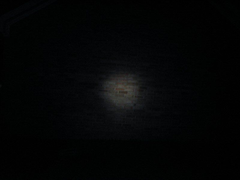
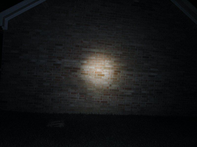
The last shots are outside against the wall of the garage.
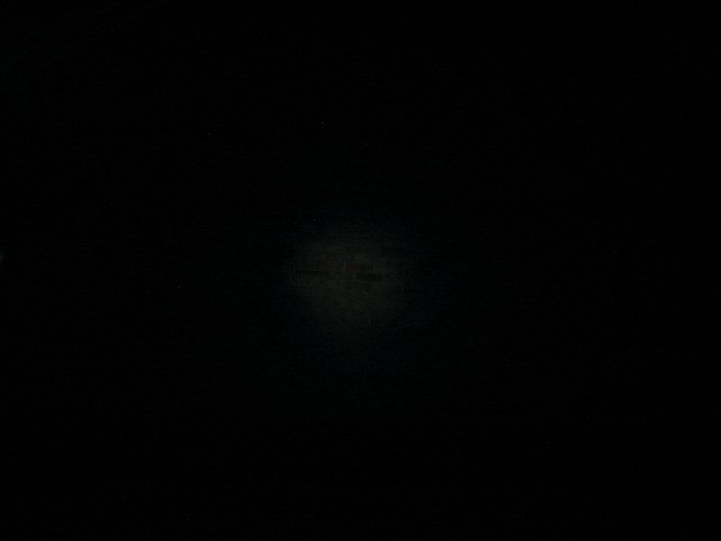
Lowest setting on the driver. It looks darker than my eyes saw.
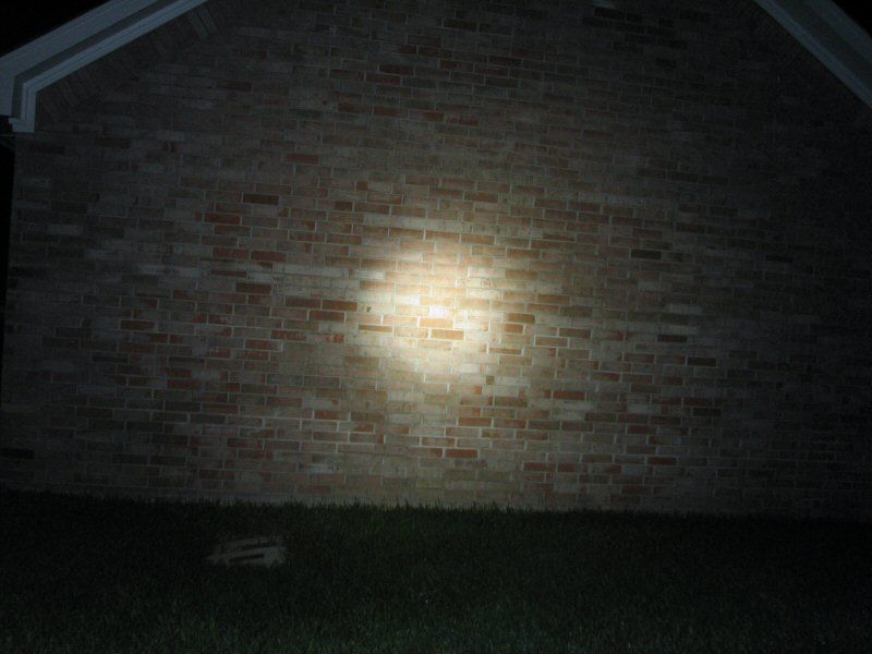
Driver setting 2, looks about what I saw
Driver setting 3, looks about what I saw
Driver setting 4, looks brighter than what I saw
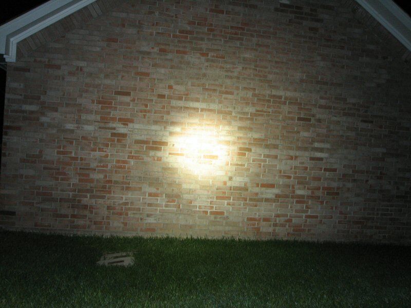
Driver setting 5, looks brighter than what I saw. Much brighter especially in the hot spot.
This one was on high and it looks much like what I saw.
That's all folks!!