Bit more planning stuff, this time on how I will be tackling the emitter mounting and how I’ll approach sinking some heat into that massive reflector.
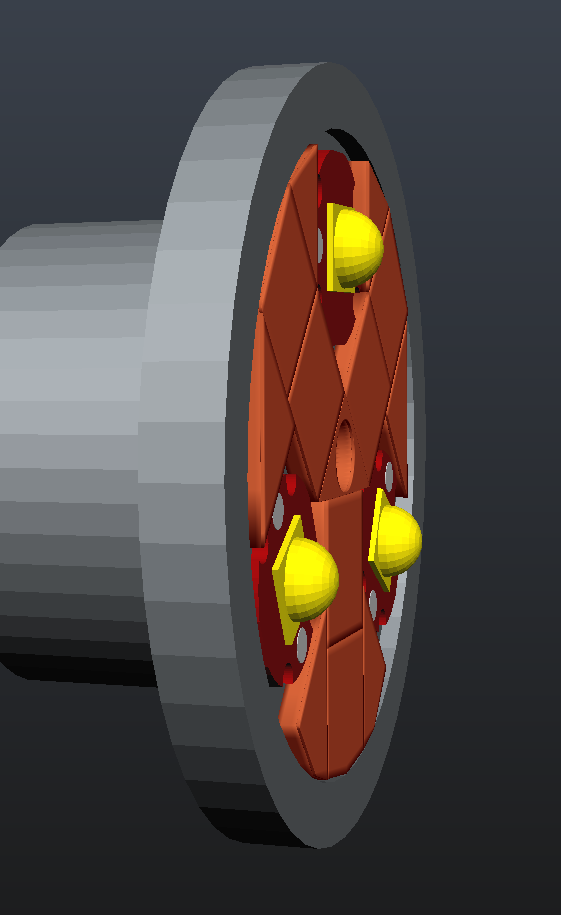
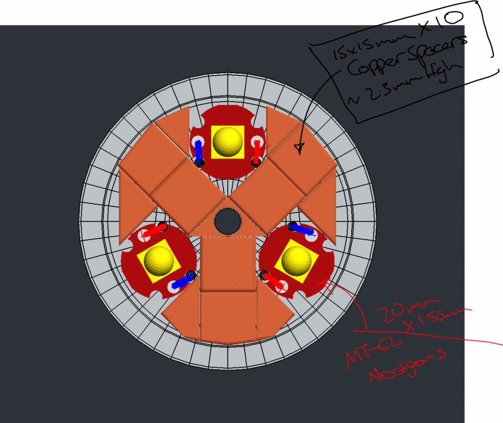
Front view showing the noctigons in place and the crazy pattern of necessity for my copper spacers :).
The idea is to have the reflector back sitting flush on these copper spacers and sucking some heat off the pill.
Would love to be able to machine a nice copper spacer/gasket for this but I’ll have to make do with what I can find.
So far I’ve found some 15x15mm copper squares on ebay available in various thickness so I’ve ordered a bunch of different packs to combine and hopefully cover my spacing needs.
Going by my measurements and Noctigon/Cree datasheets I should need a spacer height of 2.3mm to just clear the top of the MT-G2 baseplates with the reflector. (The emitters pcbs themselves will probably be glued down)
So I’ve ordered 2mm, 1mm, 0.3mm and 2x 1.2mm sets of 10 spacers so I should be able to cover any distance that’s 2mm, 2.2mm —> 2.5mm in 0.1mm increments and even reach to 2.7mm if get some crazy tall noctigons for some reason. ![]()
Of course they’re all separate little squares so once I’m happy with the fit I’ll probably try reflowing them together. Maybe in a kind of press or something that can be heated while keeping the components under good pressure to get a nice tight single piece copper disk. This sounds like a nightmare by I’ll give it a go ![]()
In the end I just hope to be able to sink some heat into the massive bulk of the BTU reflector, because in stock form it looks like there is very little thermal pathway between it and the body/pill.
For the emitter wiring I’ll need to drill 6 holes through the pill surface to get the wires close enough to each pcb solder point. I figure drilling at an angle from the places shown on my model I should just about be able to drill through the thinner part of the pill and gain access to the driver cavity without going through too much solid sidewall.
In there I’ll have to see about adding some more thermal mass that’ll bolt to the bottom of the mcpcb mounting plate.
Depends on how much space I need for drivers and such.
For the drivers I’ll be running a separate set of 7135s/(slave driver) to each emitter so while the whole circuit will still be in parallel I should gain some per emitter regulation and avoid any issues with differing vF or resistances.
So that’s it, let me know what you guys think and if anyone has attempted something similar that I can learn from.
Especially with regard to those copper spacers and reflowing stuff like that together.
Cheers