I think this is going to work: XM-size and XP-size leds can be used on the same board without compromising the functionality. Nice!
It may need some fine-tuning (like tilting the therm.pads a bit to make the current path for led #4 a bit wider), make a bit wider clear-outs of the tracing around the holes and the edge, etc.
And perhaps looking at this design people come up with more clever ideas (add XHP70 pads as well :smiling_imp: )
Thanks for the very helpfull drawing and thinking sofar, Texas_Ace, let’s let this brew a little while …
Ya’ll are too quick lol. I actually noticed the thermo issue just after posting the picture and was hoping to update it before anyone saw it. I had just tossed it out of the way and forgot to position it properly.
I updated the above picture with the pads angled properly.
The entire board will need to be redone by thorfire as I have no exact measurements to go off of plus this is something that would be best to have them do the final design work anyways since I have no idea what software they use and they need to work with the raw source files.
Naturally we need to see what the group says, just figured I would knock out the obvious things while I was in there so people and pick apart the not-so-obvious.
Two months ago I have asked for a quote for the Q8 board at a manufacturer based on my hand drawing, and even that was no problem, their engineers just re-did the drawing properly.
So I have confidence that a drawing like yours above should be way sufficient for Thorfire to make a design with all dimensions correct.
Regarding the clearance of parts and + traces around the screw holes - do you think it’s enough for bigger screw heads which Thorfire might use? Don’t want the problems which Astrolux S41 had.
Screw heads are on the bottonside of the board.
The E14/41 had the board screwed in from above to the housing, this screws from below to the reflector.
I didn’t see this anywhere, so I’ll be the one to bring it up, I guess (unless someone else did and I missed it).
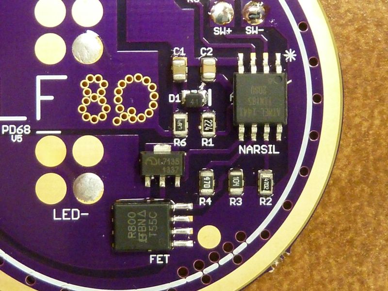
Texas_Ace, you said you turned the LED pads so that they had a larger trace size to the ground plane? Do you mean for the LED- trace or the Thermal pad or something else? I can’t see where the copper to the LED- is any bigger in your drawing than it was in djozz’s sketch. And, of course, the Thermal pads are DTP, so no traces are needed there. So, I’m not understanding what you mean by bigger traces to the ground plane.
Imagine you’re in an emergency situation (I once lost my way in a cramped wild cave and without a spare light I wouldn’t have gotten out (hope my grammar is correct :laughing:
Or you’re lost in the forest in darkness, with a super-cool flashlight which goes off for the sake of 4 cells.
I suggest making it switch to “forced low” when voltage drops below 2.5 volts, or lowest low when voltage drops even more - you still have decent light and batteries will last for hours.
Btw, I once discharged 18650b’s to 0.0 volts (put them into a stereo which turned out to have parasitic current, and left them there for a month).
I charged the batteries again and still can’t see any loss in capacity or any malfunctioning.