Quad XPG bike light

Not too long ago, I had picked up an XML bike light on sale from DX (post #301 here), so when another one (SSC P7 version this time) went on liquidation from the US warehouse for $22, I knew it would be one I’d be modding.

A test between the XML and P7 versions gave similar output and beam pattern (mostly throw). I don’t care for a throwy beam in a bike light, so the stock lens from the XML version was replaced with this wide angle lens which did a great job at spreading the beam, making it more bike worthy.

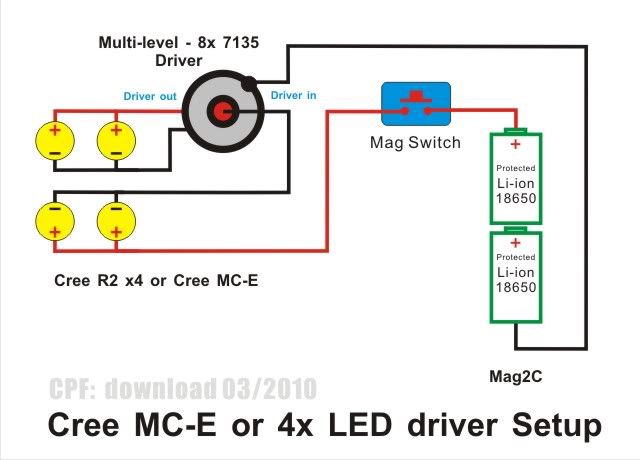
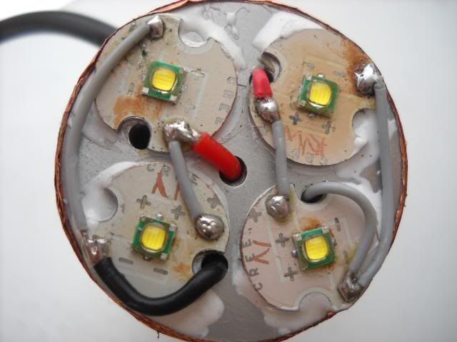
As for the P7, a quad XPG build wired according to the "poor man's multi-lux setup" (below) would be a perfect match for the 2s2p 8.4V battery pack. I have done a similar build here in a Mag 2C host and was very happy with the tint and flood/throw beam pattern. For optics, I used Tina-D that were removed from the holders. This allowed 4 to fit inside the 35mm head.

First, here is the tear down of the stock P7 bike light. Only the head, switch boot cover, mounting bracket, heat sink, and lens would be reused.

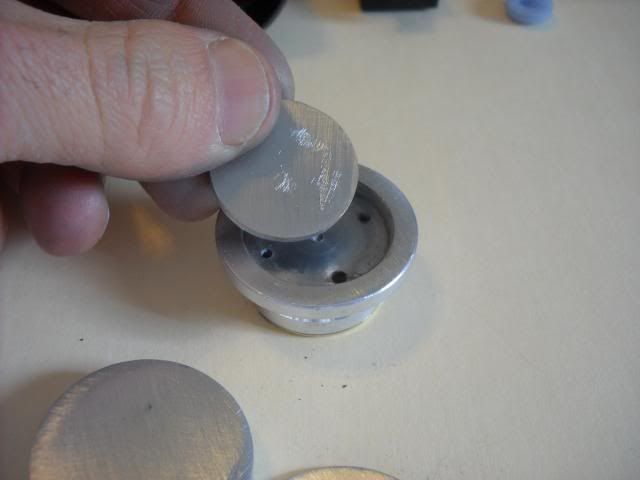
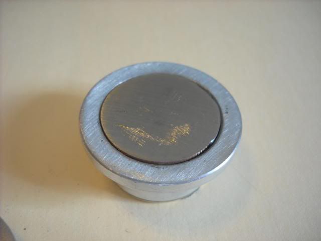
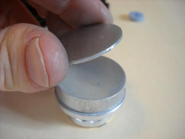
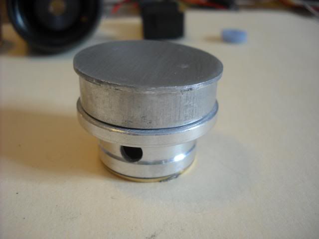
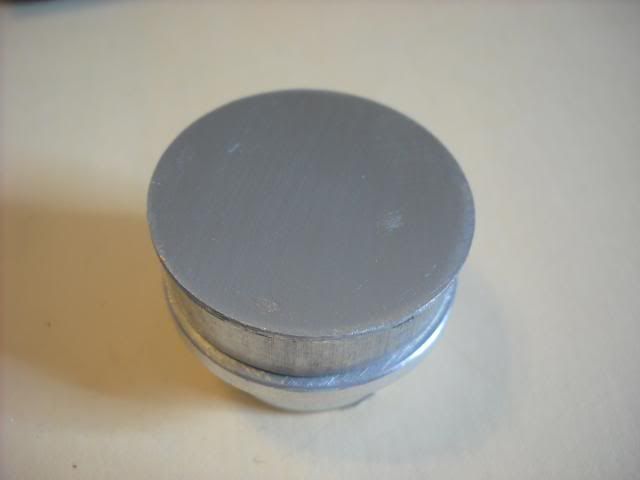
I needed to raise the emitters closer to the lens, so I beefed up the heat sink with some additional pieces of aluminum as shown below. Not having a lathe meant having to do this the hard way - piece by piece! Pieces were secured with thermal adhesive and JB weld.

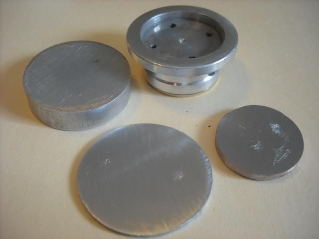
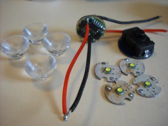
Shown below are the additional parts used.

  • 4 x XPG 5000K emitters reflowed onto ground down 16mm boards
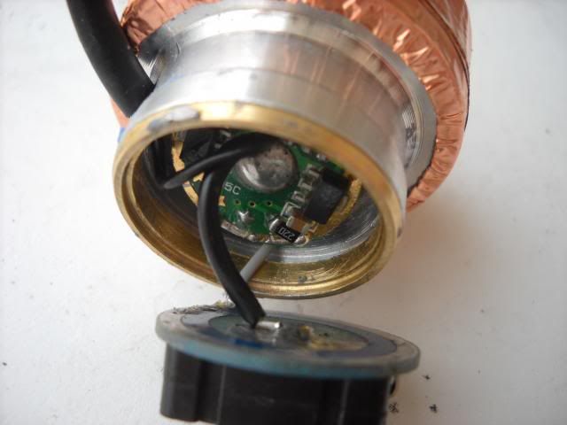
  • 2.8A driver set to High-Low
  • 4 x XPG optics with holders removed
  • Clicky switch

Emitters wired 2s2p.

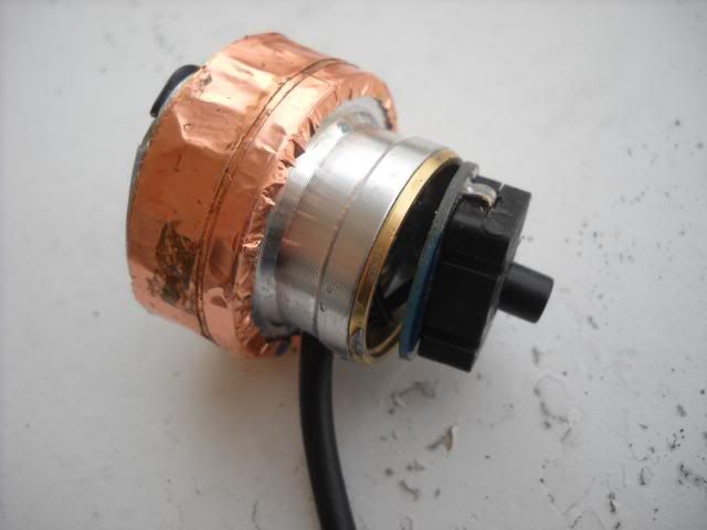
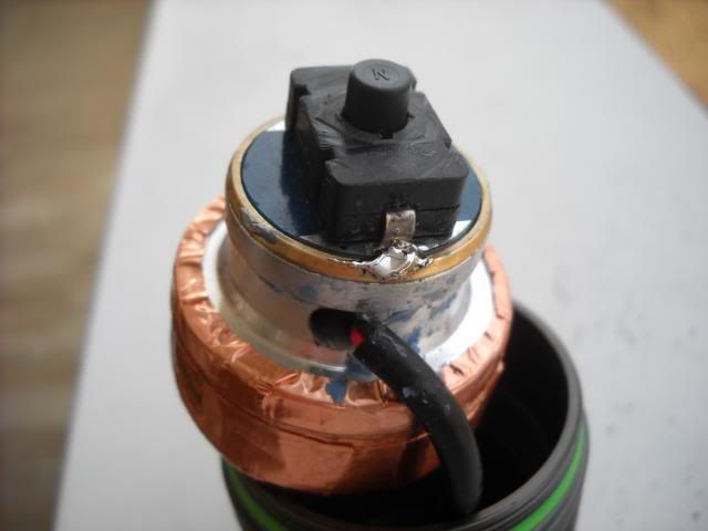
Driver and switch wired. I also wrapped the heat sink with copper tape for a snug fit into the head.
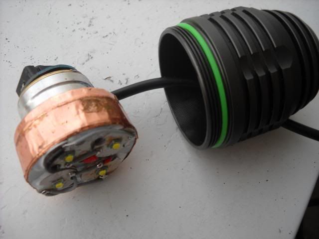
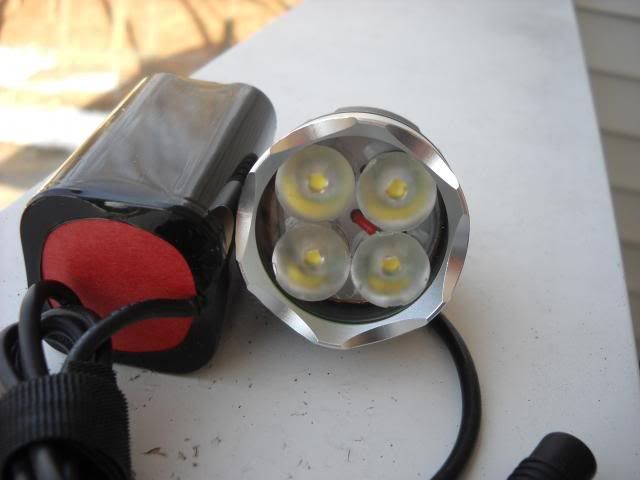
Fully assembly

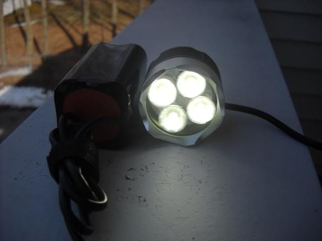
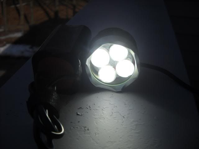
Low and High (taken outdoors in daylight). My camera does not have manual settings, but you get the idea.

I was going to do some comparison shots, but discovered an annoying flickering in the light on both low and high modes. I tested a different battery pack and still have the same problem. I will also try a good pair of 18650 or 26650 cells to make sure the battery packs are not the issue. I don’t imagine they would be, but this is drawing more current (~2.8A) than the stock driver. Many have commented on how unreliable these particular battery packs can be.

If that does not solve the problem, it may be a short or bad solder joint which would unfortunately require a tear down for inspection.

Impressive work, though I am curious why not use XM-Ls instead. Youve got the heat sinking capability, esp since batteries are located elsewhere. And youve got the space. Add a multi switch driver so you can have a High/Med/Low and you are in good shape.
I guess you are just making best use of what you’ve got to work with.

Nice build. Thanks for sharing!

-Garry

You're right. I had the XPG's already and needed to use them up. XML's would have only drawn 1.4A each and the optics would not have fit.

Thanks Gary!

I probably read your OP too fast, but I believe you said you have flickering on both modes and are drawing more current than the driver is spec’d for. If that is the case, you may have an intermittent short somewhere. From the pictures, it looks like your driver is loose in the pill space. Probably the first place to check if you haven’t already.

EDIT: Nice looking build by the way.

Correct, that is one area that is suspect. I was in a rush to get this done and did not take the time to insulate. However, to that point, I did pull it the switch slightly to visually check the driver. I was not able to see any region that would be touching the base to create a short. When powered up, I still got the flickering. I did test the setup before assembly and the light did appear stable. I'm sure it's a wiring issue, just a matter of checking and rechecking each connection.

As for the driver current, I am not drawing more than it is spec'd for. It is right at 2.8A (1.4A per LED), exactly what an 8xAMC 7135 board should be delivering.

nice job sir. hope you get the flickering sorted quickly. :bigsmile:

Just in case you didn’t see my edit. That is a nice looking build you did there. The pictures are great. I need to find me a budget camera that does clear close ups.

Looking at the 11th picture down, the two negative connections towards the top of the picture look like they may potentially be making contact to the pill. The solder blobs look like they are approaching the edge of the insulating layer. I don’t know if that would cause flickering problems. Guess it depends on if your driver regulates via the negative path. Seems like it could cause problems either way. I’m no electronics expert, but I think it can create what are called ground loops.

This is a real nice build you have made. Keep us informed on the flickering fix. Cheers.

Thanks gords!

Thanks 4wheeler. I did see your edit!

My camera does ok with macro shots if the lighting is just right. Typically outdoors away from direct sunlight is best. Indoors, usually not so good. It gets grainy or the colors are off. It also has a hard time focusing when I am too close to the subject.

Yes, the solder joint at the edge of the driver is close to the pill walls. I have pulled the unit apart slighty and disconnect the solder joint connecting the switch to the pill. I ran it this morning for a few minutes on both low and high with no visible flickering, so I know it can be fixed. I'll just need to better insulate the expose solder joints and driver.

Thanks! - I'm getting there and will post when solved. Thanks MrsDNF!

Good to hear about your progress. I just looked at the wiring diagram. What is the input voltage range for the driver you used? I ask because the diagram shows 2P emitters feeding the driver. So the voltage from the batteries will drop by about 3 volts (whatever the Vf is) before getting to the driver.