Part of modding is to work with what's available and be creative when you don't have or want to buy lots of parts. I am in need of a momentary switch for a Maglite and I want to just use the stock switch and housing. Here's a way to make it momentary and use it for that purpose, while still providing a non-switched path for the positive.
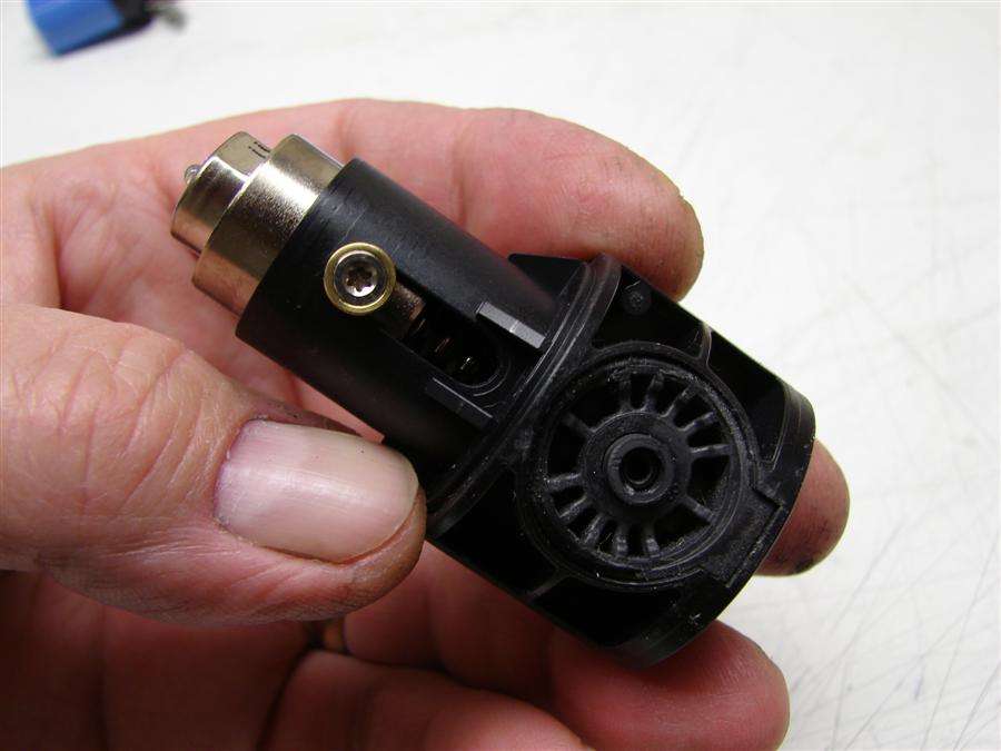
First thing to do is tear it down. It's easy, the switch just pushes out from the bottom. Just be careful of the negative contact on the bottom, (the one that has the hold down screw in it). It wants to stick in the switch as you push out.
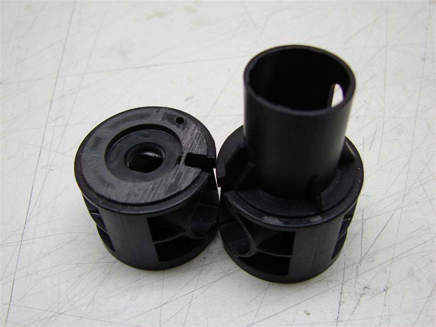
First mod is to remove the tower. I won't be needing it, so I cut it off with a hacksaw.
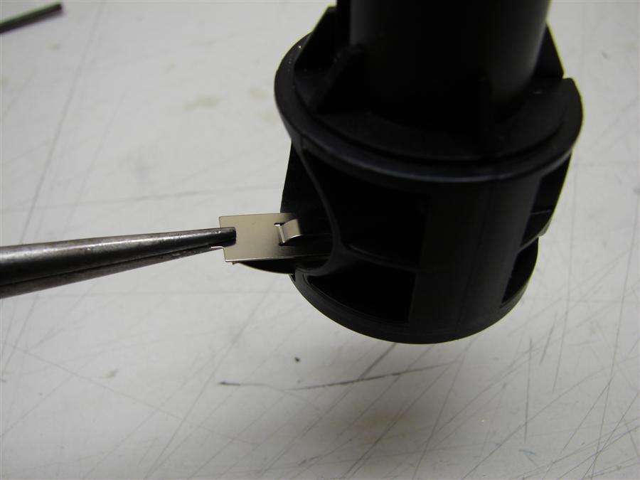
Next, I pull out the positive contact plate out of the housing. I won't be using it.
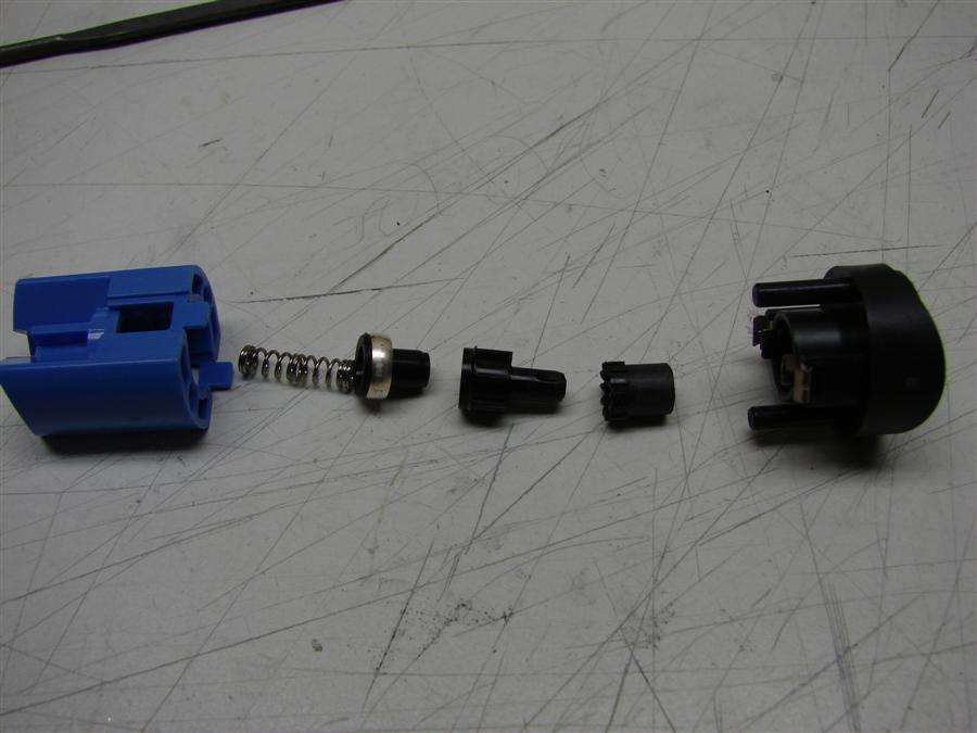
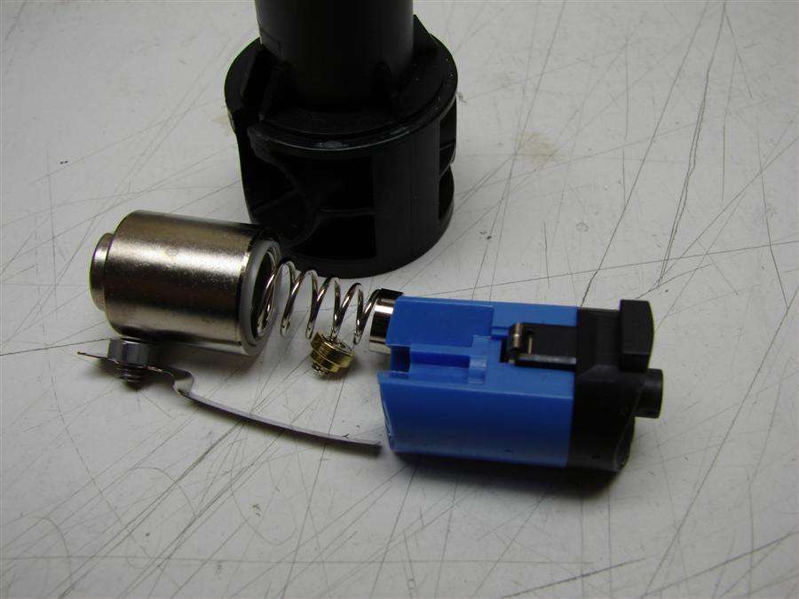
The switch pulls apart easily, just watch for flying parts. In Order are the blue bottom half of the switch, the spring, the plunger with the metal ring contact on it and the two piece plunger that is what you push on for on/off and the top section of the switch.
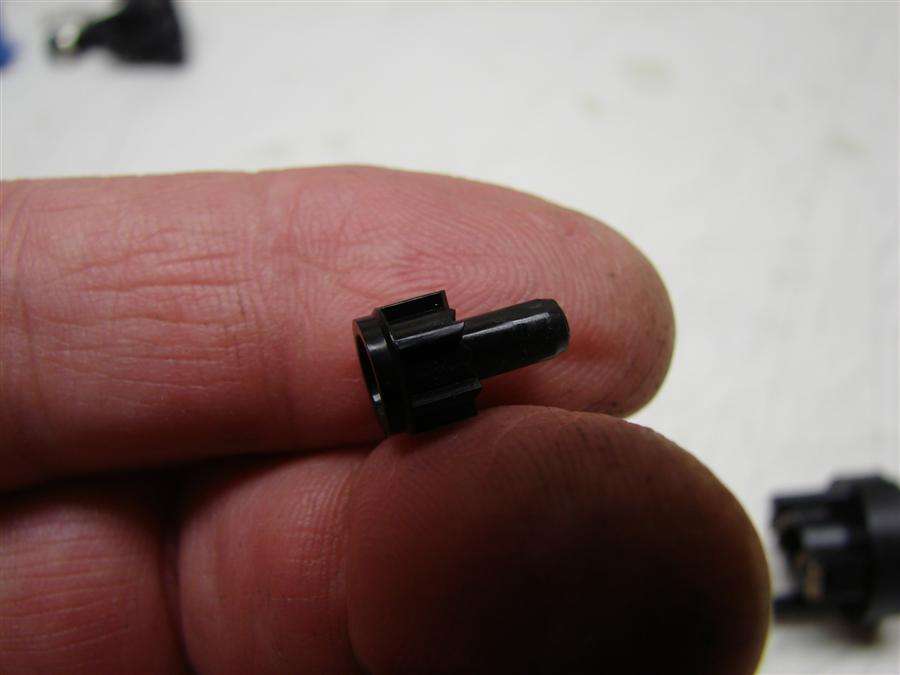
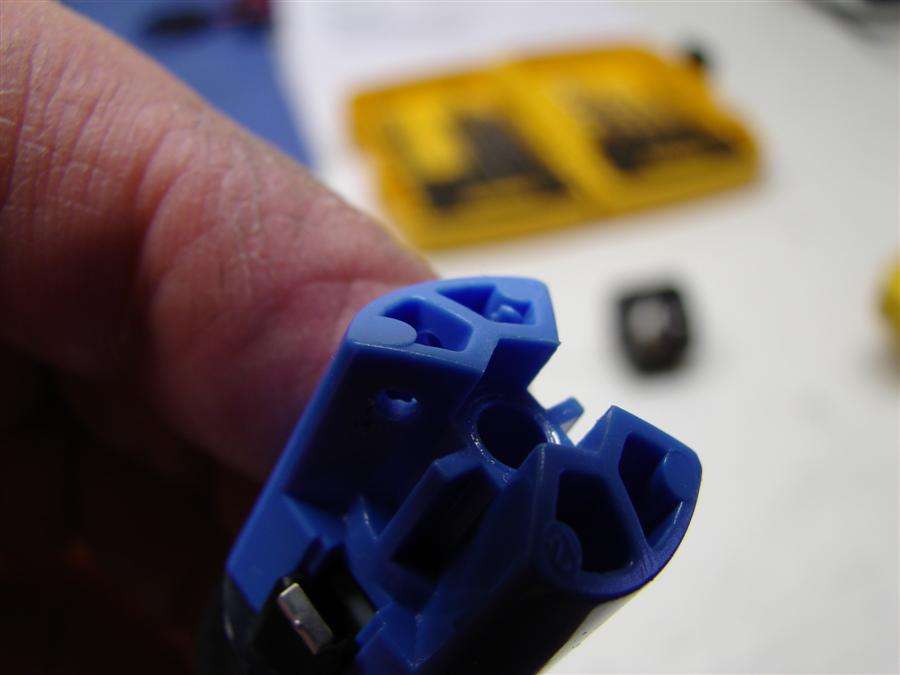
What I want is this piece here. It's the lower part of that two piece plunger and I need to modify it, so it does not index any more.
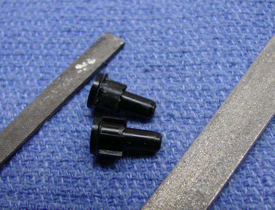
I just use files to file off the fins, so it's just a smooth plunger. Now it will not index or catch on the prongs inside the upper section of the switch any more. It will make when I push in and break when I let off.
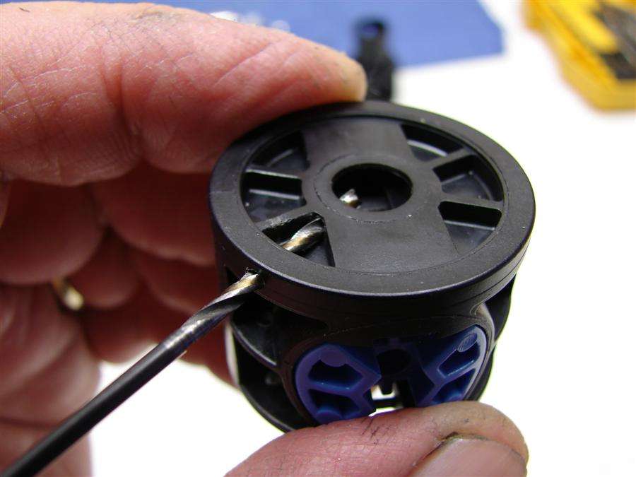
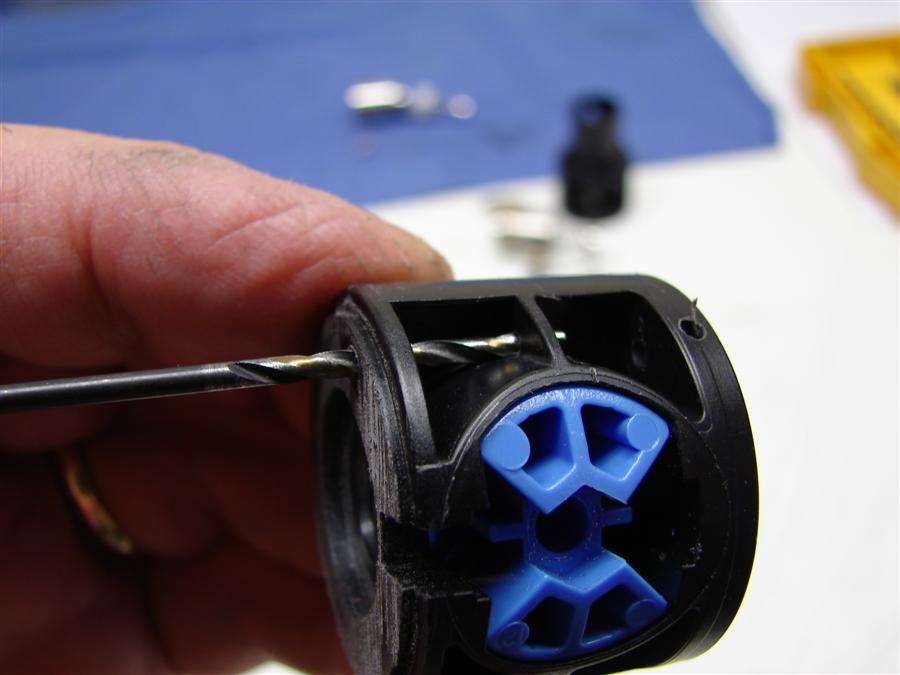
Now, I want to make it work for a driver like the DrJones linear drivers, so I need two wires to that driver and I need to fit them in, so it does not interfere with the rest of the switch. Plus, I am drilling holes to make a new path for the Positive wire and these are the holes I drill first. I am drilling here with a small bit. 5/64" is what I use, but it's dependent on the size of the wire. I don't need heavy wire, since it's only low amps on this build.
Then I drill thru the housing here, from the front, thru the center.

I drill a third hole here, from the back to the center.

This is the new path for the Positive wire. I will solder a copper disc onto the wire and glue it to the back of the housing, for the battery contact.
Now I drill thru one side of the switch itself. It's near the top edge of the bottom half of the switch and this will carry one of the two wires needed for the driver, to control it with a momentary signal.
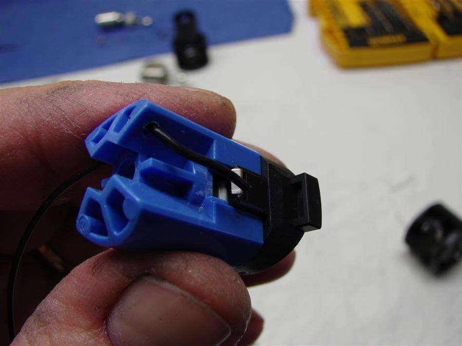
The wire is fed thru and I will solder it to one of the contacts of the switch. This is the side of the switch that faces toward the positive. It was the side that used to touch the battery contact.
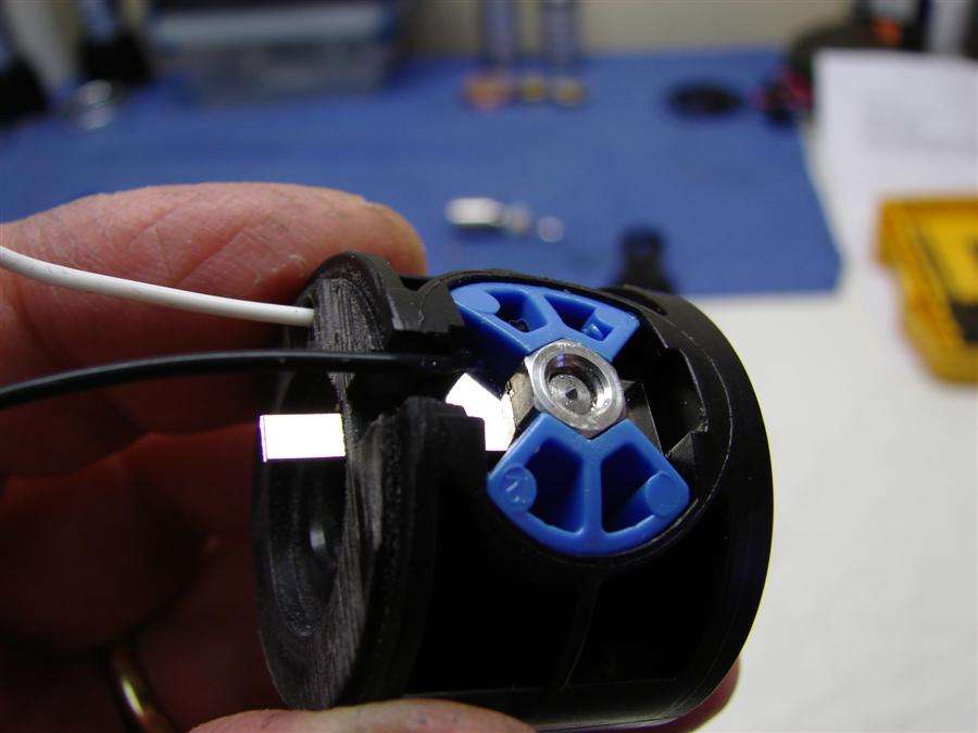
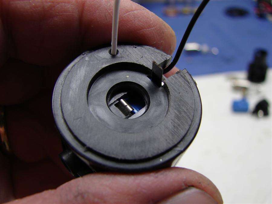
I have the switch back in place and the black wire comes out right above the original metal negative contact, where it won't interfere with anything. I left the original metal negative contact, so I could still tighten the switch in the body and in case I needed the contact for a negative path, I could solder to what's left of the metal tab.
The other wire for the driver is soldered to the switch contact on the side that would face the heat sink/led/pill assembly. I now have power thru the white wire and the two wires needed for the driver and a momentary switch, without having to buy something else.
I guess that's about it...