There has been much discussion on the XM-L and driving this in vogue emitter to its potential.
The highly touted AMC7135 350ma current regulating devices are becoming more available these days.
I purchased 8 of these units for $0.50 each for the very purpose described in this post.
I opted to drive the 16mm XM-L T6 module at 3.15A by taking the slightly lacking 2.8A NANJG 105C driver (this one from Illumination Supply who also offers the AMC7135's) and adding 1x AMC7135. And figuring how to best apply the extra device.
I also opted to glue the emitter to the pill using Arctic Silver Thermal Adhesive. Great stuff but be warned, this particular one sets very fast... pot life of 5 minutes. One 7 gram kit will last you a lifetime of DIY flashlight assembling. I chose this route to maximize thermal conductivity and to make sure the emitter didn't float or turn with the reflector. This is also why I picked the 16mm module. Compared to Fujik, a silicon based product, I consider the Arctic Silver much more thermally conductive. Others may argue this but I've convinced myself... and that's all that counts. It is worth noting that the Arctic Silver epoxy is quite permanent! ...where silicon can be removed with relative ease. If this was an XP-G or XR-E, no question, Fujik would be fine. Enough for this soapbox speech.
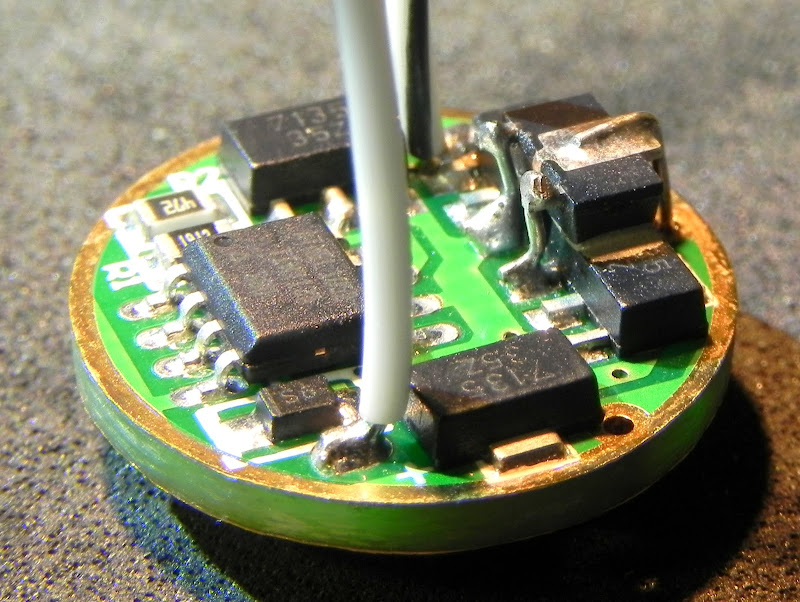
Fortunately, the fact that I was mixing up some thermal epoxy anyway, and I needed to attach the AMC7135 on the emitter side of the driver, I decided a couple of small dabs of epoxy on the AMC7135 would help heatsink the extra device to the lower 2 devices I choose to heat-share the new device. I chose to invert the device so that wring would be simplified.
9th AMC7135 thermally glued to the NANJG 105C driver:

I trimmed the middle lead (ground) on the extra device again, to simplify wiring:

I used the aligator clamp fixture to hold the 0,4mm wire for soldering the leads in place. You want to solder everything with planty of lead length to help hold things in place, then trim the wire with a sharp pair of flush cutters. A steady hand and some very strong reading glasses go a long way to making this easier to do.
I also opted for some 24AWG Teflon wire from Illumination Supply. This is a high strand count wire with a very stiff insulation. Not most people 1st choice for wire, but for what I wanted, this is appropriate. When working with Teflon insulation, it is easiest to circumcise the wire with a hobby knife. Once tinned, trim and form for use. The beauty of Teflon is that it doesn't melt. If suppleness is desired, silicon rubber insulation works best.
9th device terminated and the driver wired for emitter:
The ground wire was terminated on the battery side to avoid interference with the pill; I also choose to jumper the driver for 3-modes. Tip: scrape the silkscreen before soldering the jumper. Also notice the ground spring.
Battery side termination and ground spring:

Holding the pill and driver for soldering is critical in this case as the emitter is already in the pill. I find a paper clamp most convenient for making the pill-2-driver termination. You see a little lux on the pill. I prefer 3 solder-spot.
Preparing to solder the driver into the pill:

Once the pill cooled a little and I turned the pill in the clamp, I was able to make the 3rd termination. Once done and cleaned with alcohol, the driver is pretty much commited.
Driver snug in the pill:

Since I use lots of heat, flux, and solder in making the pill to driver termination, it does require a little cleanup so the solder does not interfere with the large spring. I use a hobby knife to scrape the blobs into more manageable shapes. The solder removes easy enough.
Solder connection scraped with hobby knife:

Now is the time to terminate the emitter. This is the crucial step where you can totally destroy your work or make out like a bandit. I suppose I should consider myself lucky... it went fine. I had to pre-form the stiff wire and determine how long to cut it off (commitment #1), then decide on where to trim the insulation (commitment #2), and then try my best to circumscribe the insulation with a hobby knife and not nick the emitter dome. Yes, I got lucky... all went well. Next, I had to make the termination to the module: I squished the wire so it fanned out; tinned the wire; fluxed the pad lightly; and added heat from the iron while holding the wire against the pad. I grew an extra arm and hand to accomplish this. In this build, the wires are coming straight from the driver to the emitter. No extra wire tucked away, no offset... "direct drive"!
Soldering the wires to the emitter:

I modified a reflector to hold the emitter down in the pill while the epoxy cured. The idea is that the relief would also clear the wire terminations. This is another reason to use the 16mm module as the wires are that much further to the side. This reflector worked great for getting the emitter to protrude into the reflector as far as possible. It mimics the Manafont reflector that is designed this way. The Manafont reflector, however, is a much better solution for this configuration. It doesn't have the flat area at the emitter and throws a much nice beam.
Modified reflector for max emitter protrusion:

I also modified the pill in several ways to make it a bit more user friendly. I made the driver fit easier and deeper, and I lowered the lip above the emitter so it would screw into the reflector further. This isn't necessary for the Manafont reflector, only modified XR-E reflectors.
Last but certainly most important is the insulator. I found some unused Nomex or Kapton tape from a yarded driver and made quick work of slicing a square out of the center. Trimmed the corners and burnished it in place. Now I can bottom out the reflector and not worry about shorting the emitter.
Nomex insulator added:

When all was done and checked for shorts and opens, I set up to test the unit. Once I learned that the switch I was using is insufficient for the load, I could read 120ma in low and 950ma in medium. High pegged the meter but I am quite sure I am hitting the 3.15A as sought. I say this because this same driver is only 800ma and 100ma in the 2.8A configuration.
I put this module in the Sky*Ray S-R5 and quickly learned about one of the limitations of this driver; that little pring isn't long enough for all lights. I had to remove the battery retaining ring from the Sky*Ray and it worked fine with my long 3100mah Panasonics as well as the standard non-protected cells. Just something you want to be aware of when building the driver. One could add a slug to the spring during the build or afterward if they so determined this advantageous.
I will do some throw tests tonight if it doesn't rain. From what I can tell so far, this P60 is right up there with the 2.8A 40mm V-Shark recently modified with this same driver. If it keeps up, it would be good as the P60's w/ XM-L isn't getting the rave reviews that the bigger reflectors get. And that V-Shark is a really nice thrower.
One last tip: I ground both ends of the large spring to give it a flat contact area. As the current goes up, you cannot do too much to help pass the current from the battery to the emitter. I use the Dremel carbide cutoff disks for making this an easy task to accomplish.
That's all for now!

 !
!