I just received a 2-cell zoomie that I bought from ebay and took it apart right away.
I found the same driver shown by RaceR86 from this post .
A quick search found this datasheet for the cx2817.
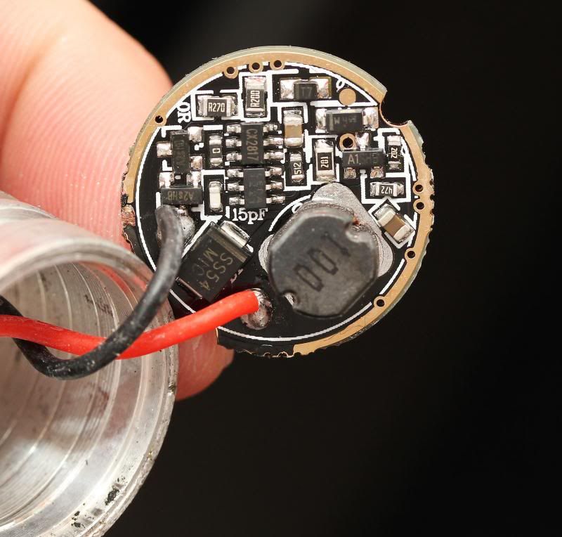
The datasheet describes two modes: Mode 1 with High/Low/Flash and Mode II with High/Medium/Low/Flash/SOS. Pin 2 is used to select the mode. From the picture of the driver, it looks like pins 2 and 3 of the CX2817 are connected to the 0 ohm shunt resistor to its left. I removed the shunt and the light now works with three modes instead of five.
It’s an easy mod until I can get my hands on a better 2-cell driver.
No, this driver is for clicky switch not digital switch. I haven’t tried it but the pencil lead trick should work since that cap provides backup power to the chip.
Pencil lead mod confirmed to work. I bridged the capacitor to the right of CX2817 in the above picture with pencil lead. The first attempt resulted in a 1-mode switch because I put too much. The second attempt resulted in loss of memory after 1 second. Now I have a light that turns on in High mode every time.
Since you could solder, you could put the flashy modes back in then put a resistor over the cap, I notice depending on the humidity my pencil lead mods sometimes work faster or slower.
Anyone know a the resistor amount to get a good 5 second reset (physically solder a resistor across the capacitor)
I think I read someone said something like 200K or something?
I detest blinkies. Having to cycle through them with next-mode garbage drivers is why I do NOT buy more of that crap.
The few garbage driver lights I have are now tolerable, thanks to the simple pencil mod. I have mine reset to HI in approx 0.5 second. That’s fine with me. And I didn’t have to microscope-solder teensie chip resistors.
In rough numbers, I remember my penciled resistance around 300Kohm. Maybe 250Kohm-350Kohm. From salvaged laptop battery packs, I pulled some resistors in this range, and sent them to a buddy. He never used them.
That’s generally where I like to end up, probably in the 0.5s to 1.0s range. 5s does not make much sense for mode switching IMO, even 2s is a long very time in that context.
I think the required resistance will vary between applications although I’m not really sure why.