Previously titled “[WIP] 20mm single sided & 17mm double-sided ?-amp linear driver which nobody wanted ;)”
This is not my most beautiful looking work. I’m only so enthusiastic about the driver in fact. It is a work in progress, please do not assume that it will work properly.
Here is some information:
This driver is a linear driver with PWM. Like a Nanjg-105c or QLite, not like the led4power LD-1.
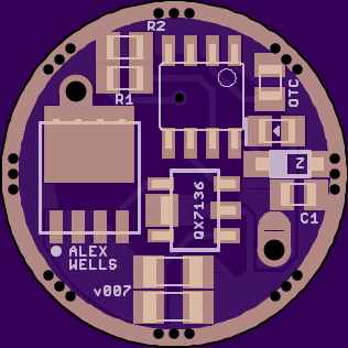
The controller is a QX7136. This is not the same thing as a 7135.
It uses sense resistors to set current.
‘Current Sense’ voltage is 50mV, probably similar to what a 7135 is doing internally? The QX7136 claims to have a 100mV dropout, 20mV lower (better) than a 7135.
Uses a Power-SO8 FET like other recent stuff. (LFPAK56 & etc.)
Features:
1mm component keepout around the edge.
1mm solid GND around the edge (no other traces extend into this area).
Zener ready.
Offtime ready.
Single sided.
1.2mm LED+ and LED- vias.
Two 1206 sense resistors.
I expect performance to be similar to a single channel of the Supfire M6 driver.
The 50mV sense voltage is lower than some other drivers. Due to the low sense voltage, extremely low value sense resistors are needed. For 2A you’ll need a pair of R050, for 5A you’d use a single R010, for 10A you’d use a pair of R010, etc.
I am going to sound unedumicated here, but whats the point of this driver? is it like a 7135 driver, but just with a different method / components? Or is just simply higher amperage? like a fet/7135 crossover?
It started out as a 17mm driver, but would not fit.
It should be able to supply pretty high current. It doesn’t require a pile of 7135’s. It all fits on one side. A normal single-sided 7135 based driver of this size might fit 5 or 6x7135, so maybe ~2.3A max.
Hmm, that reminds of of a feature I forgot to implement… I was thinking that it would be nice to implement a bypass where the ATtiny could pull the Gate pin on the FET high for “turbo” type stuff. There isn’t space in the current layout, but an air-wire could easily do it. EDIT: yes there is… clearly Pin5 and the trace it needs to connect to are right next to each other. Oops.
When I get more motivated I’ll take another stab at cramming this into 17mm. While the LD-1 is clearly a superior driver for single cell applications and hotrod SRK’s… this driver can run an MT-G2.
I forgot: the other point of this driver is that I got confused and bought some QX7136’s thinking that I could do something with them I could not. :~ So I needed to make something to use those up.
It should work fine in that application. The MCU would run the same code as normal, STAR & etc. Pinout is the standard pinout used by most ATtiny13A based drivers here on BLF. A DrJones MCU would be fine as well.
What’s the calculation for the power rating required for the sense resistor’s?
The issue I ran into trying to use 1206’s in extremely low value’s for sense resistor’s in some of my drivers was that there just isnt high power rated 1206’s out (very very few 1W and a few more 3/4w) and there’s only one brand of those (vishay dale) and they’re VERY expensive and there isnt a large selection of them available in small quantities.
You simply calculate the power dissipated. Current multiplied by voltage drop. In this case the voltage drop is extremely low, so Power is as well. At 10A drive current you’re looking at 0.5W total (0.25W per resistor). At 20A you’re looking at 1.0W total, 0.5W per resistor. That should be easy to purchase at a fair price. ($0.40 to $1.00 each in QTY=1)
I think you may have been using a relatively high sense voltage?
I should point out that anyone who plans to run 5/10/20A? through one of these should plan on heatsinking the FET properly. Potting it in epoxy is probably a good option. This driver is also compatible with the ‘remote’ boards led4power posted on OSH Park. The same wiring and cautions apply.
Also, if you setup your driver for 5A and then use the turbo bypass business to achieve 15A you will take the sense resistors beyond their ratings. I wouldn’t worry too much about it as long as you pot them. Or just don’t use the turbo bypass stuff, it’s not necessary.
If you start with the knowledge that your setup will do X-watts in DD and work backwards you can establish a safe regulated current so as not to take the sense resistors beyond spec. For example, say you know that your light will do 20A in DD. We’ll be splitting 20A between two resistors, so 10A per resistor. If we can afford a pair of 1W resistors for this project, we can use an Ohms Law calculator with that and the 10A figure and establish a resistance of 0.01 ohms. So with two in parallel we’d have 0.005 ohms, which works out to 10A regulated. Therefore for a light which does ~20A DD (turbo bypass) we’ll need to regulate at 10A for regular modes in order to keep the sense resistors in spec. As I said, I expect that we can exceed spec with potting.
I’m interested in this driver, I have lots of 7136’s (and everything else too). Would you be willing to send me your files, or at minimum your .sch and I’ll make my own board?
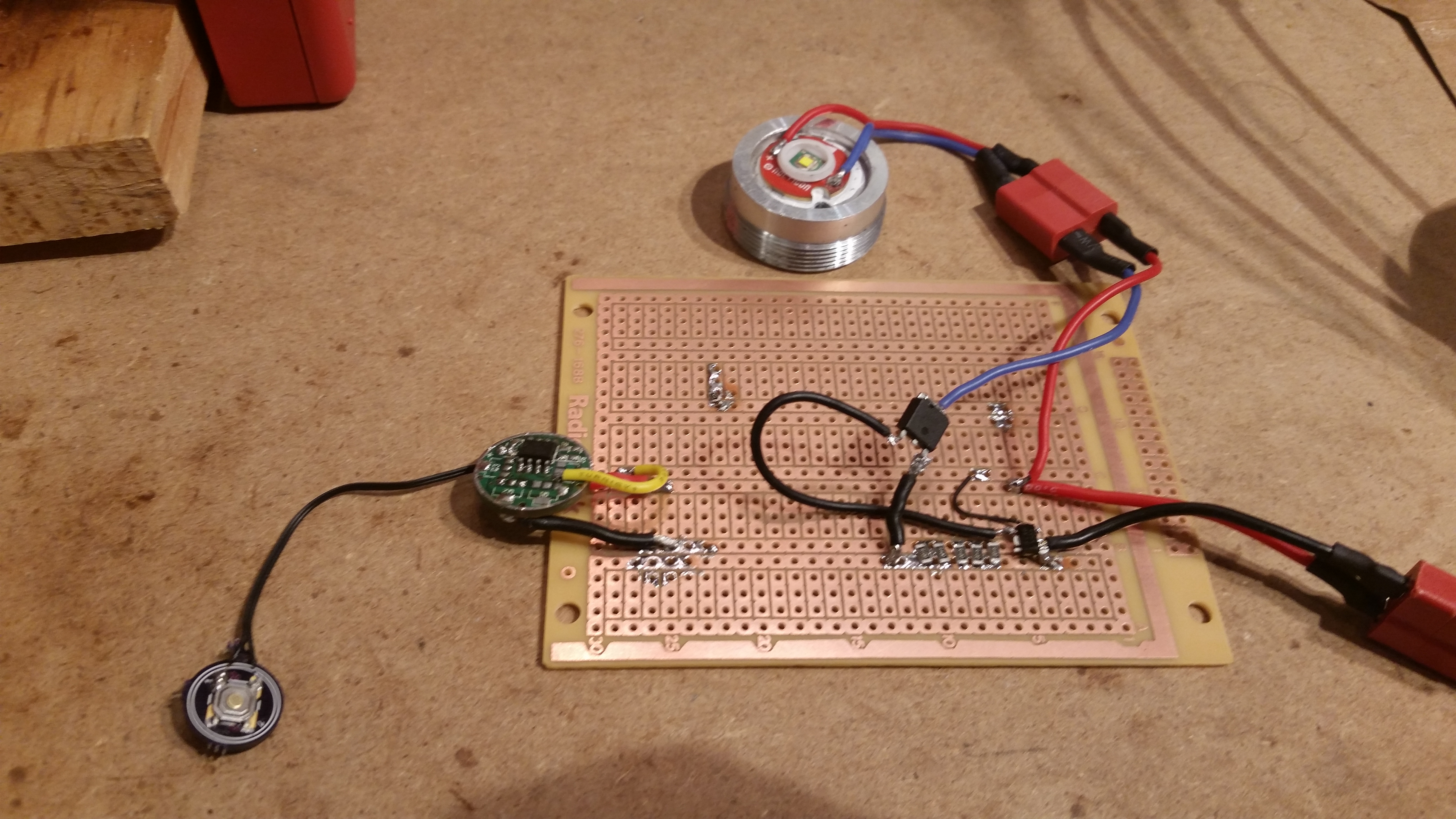
Well, I’ve just done my first test of the QX7136. It seems to operate as expected, no surprises. I used a small bank of FastTech R100 1206 sense resistors - I started with 3x and then moved to 5x.
Based on the results I got, I think these FT components are around 0.105 to 0.110 ohms. 5x of them gave 2.29A, close to the expected value of 2.5A but no cigar. About right for R105-R110 though. I measured the voltage across the bank while in operation and got 0.049v - I have little doubt that my meter is off by 0.001v and the little IC is right on point.
We’ll need an FET better suited to this purpose than NXP PSMN3R0-30YLD or Vishay 70N02. Supfire’s M6 driver uses Din-Tek 30N02 (DTU30N02). Unfortunately DTU30N02 is a DPAK part, making it rather large (phsyically) for this application. I don’t fully understand what makes this part a better fit than the other FETs, but I’m working on it. One clear difference is the Threshold Voltage.
Maybe Vishay’s SiR800DP is a good option, datasheet link. Gate charge is higher than DTU30N02, but still in the range of what I think is reasonable (someone correct me!). Drain and dissipation are higher as well, not that they matter at this level (both are very high/good). Also, “Applications” listed in the datasheet are similar.
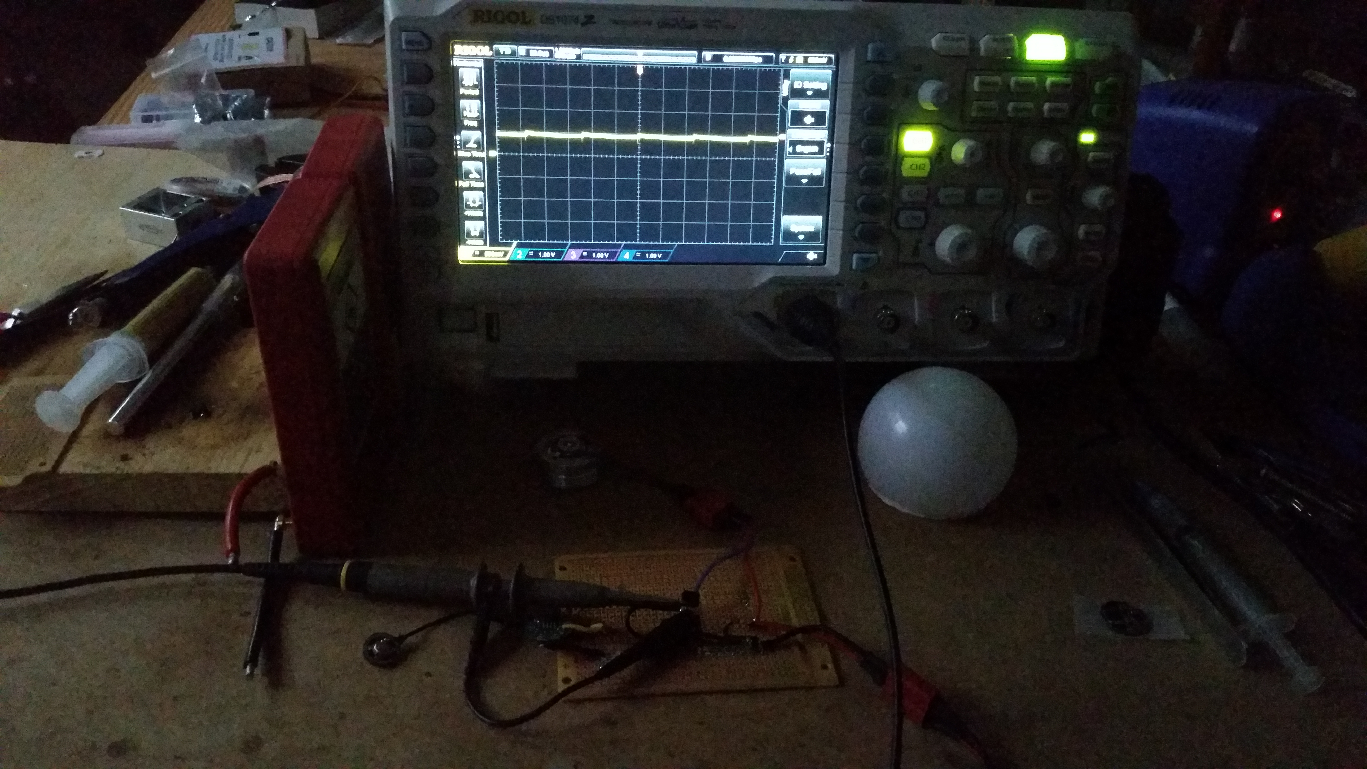
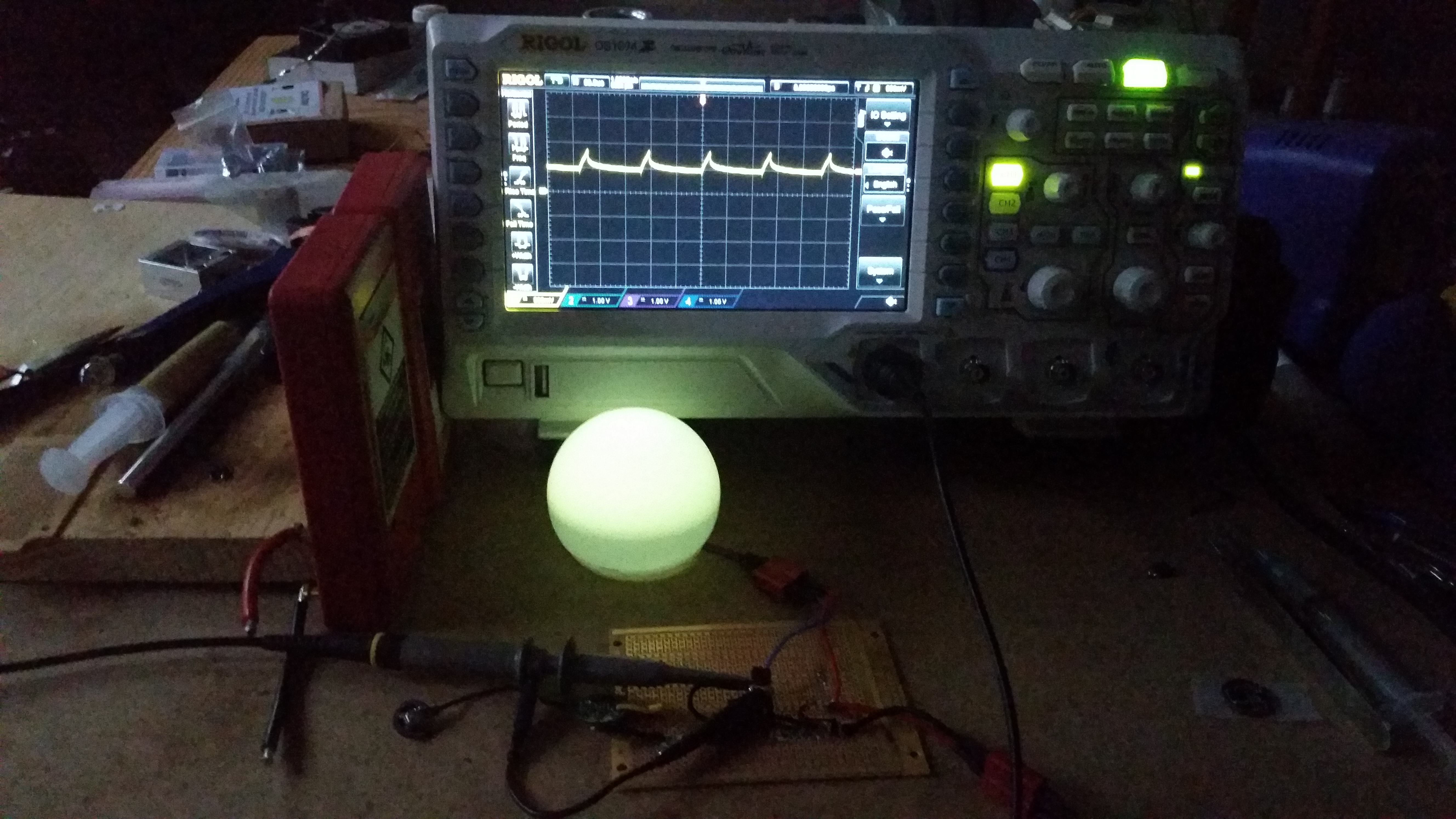
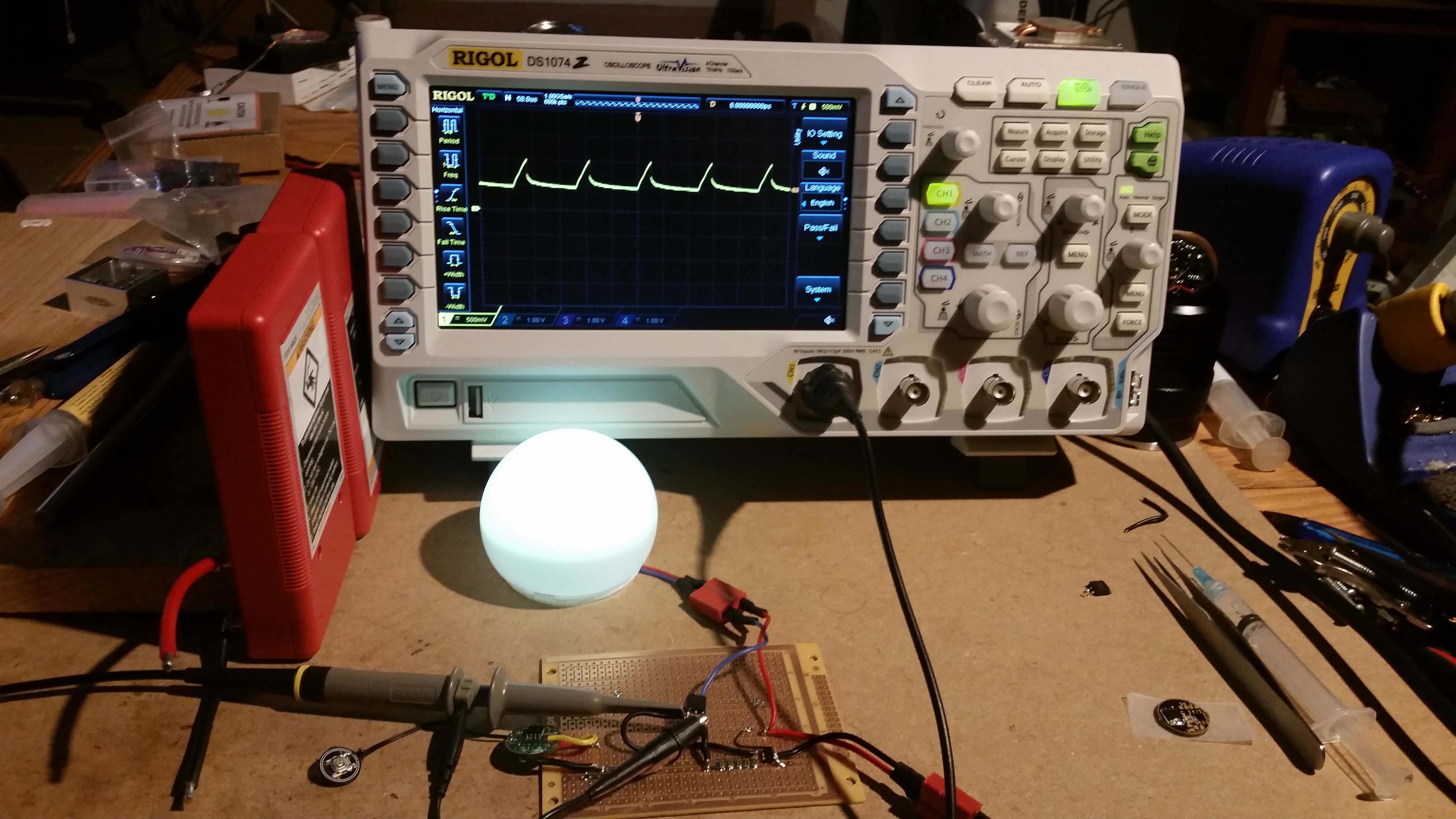
Here is my stripboard setup with a DTU30N02 and 4v input. As before I’m setup with 5x cheap R100 which achieves a regulated 2.29A
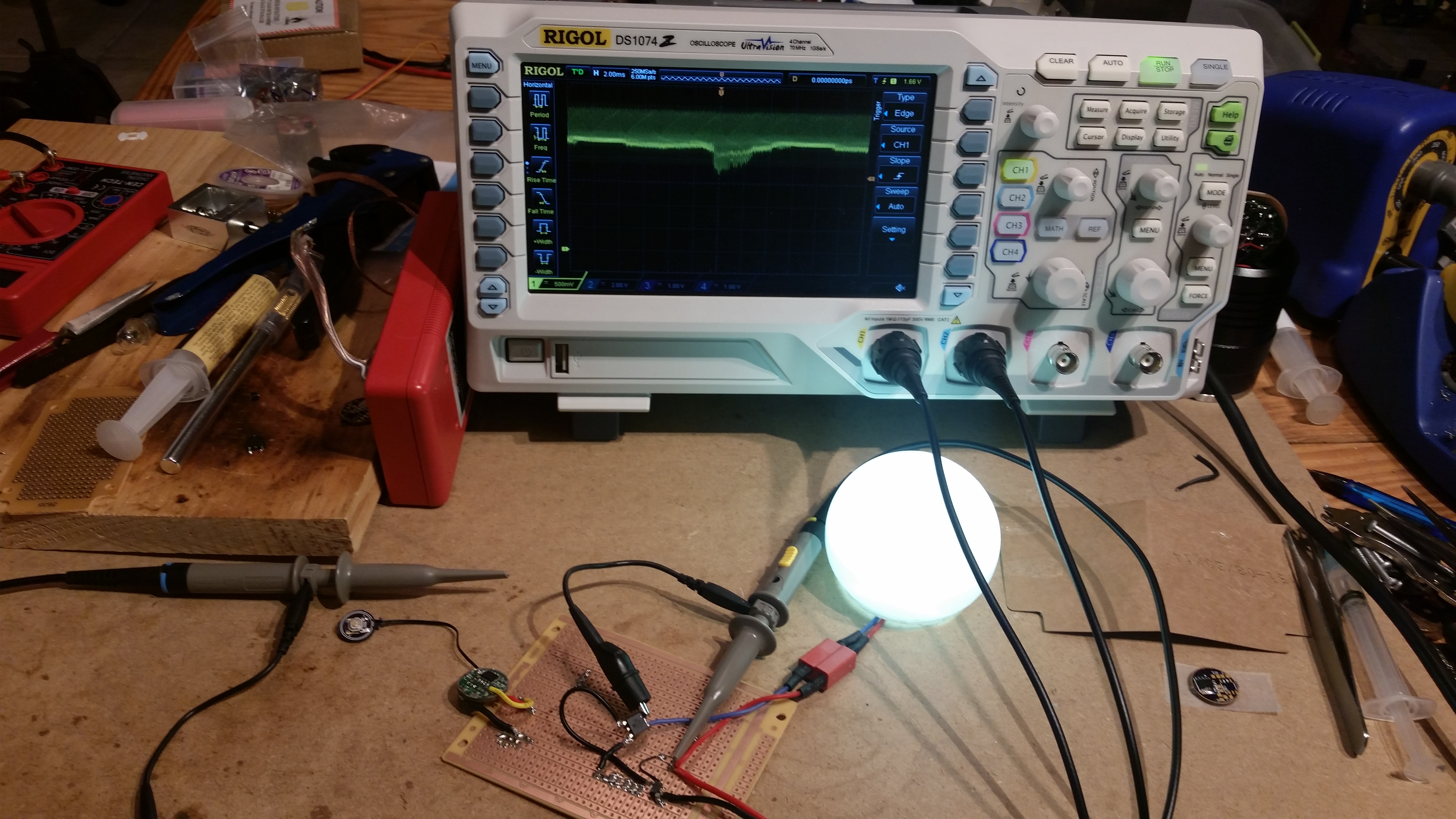
At the lowest output levels the scope’s interference is too much for the QX7136 to cope with, so output flickers and the waveform shown is inaccurate. Here is a “big picture” shot of the waveform generated at a “low” level.
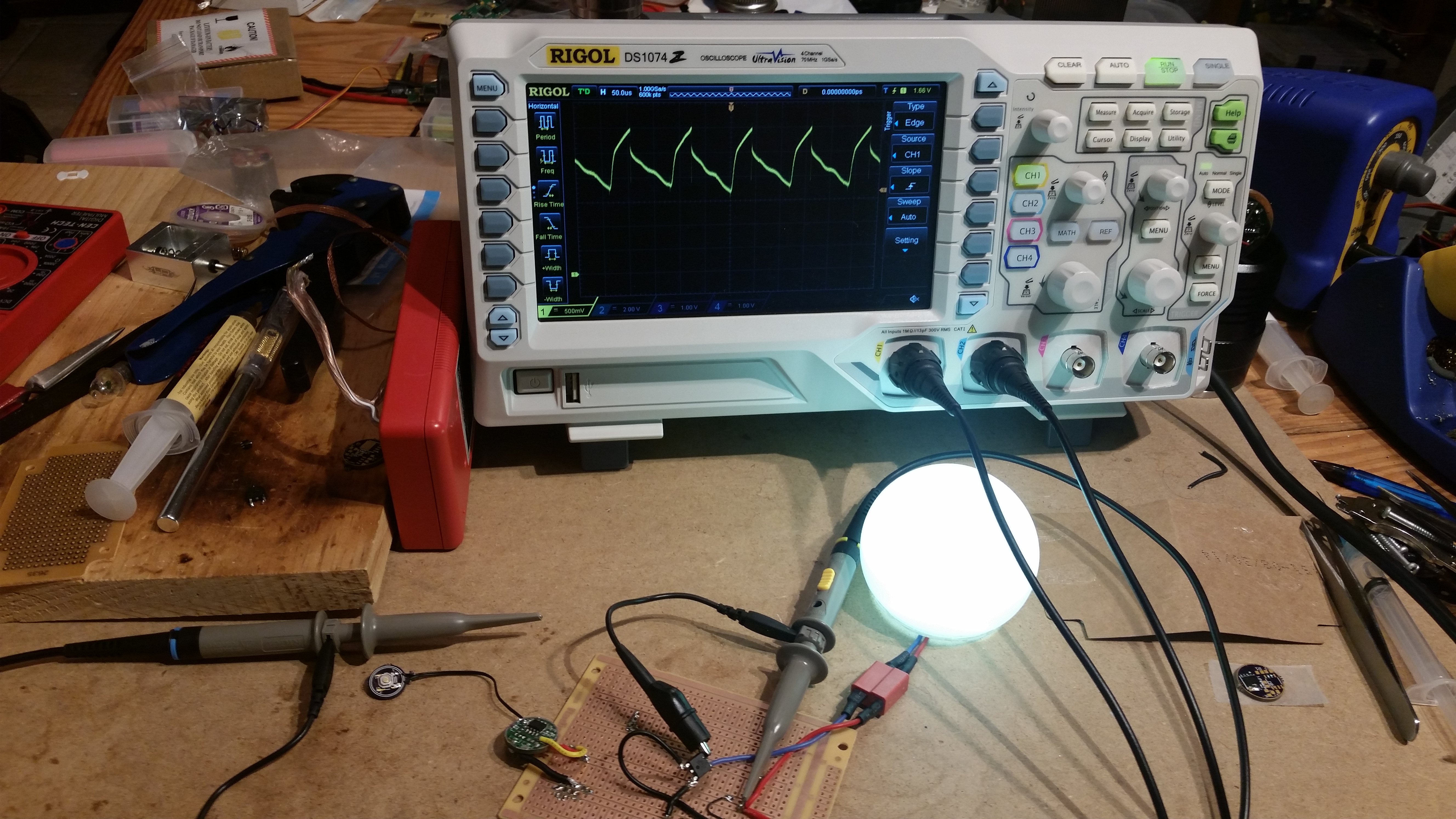
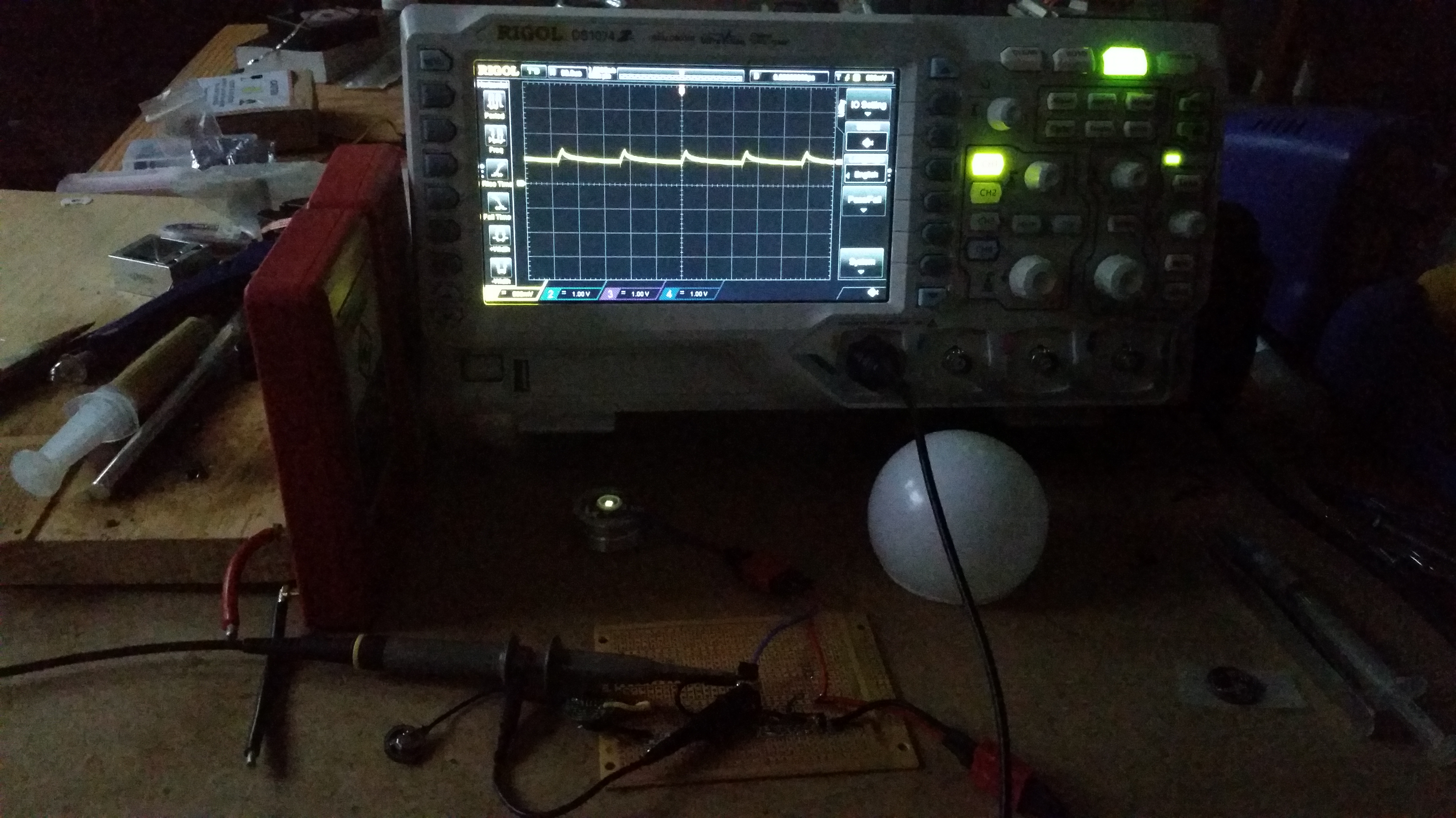
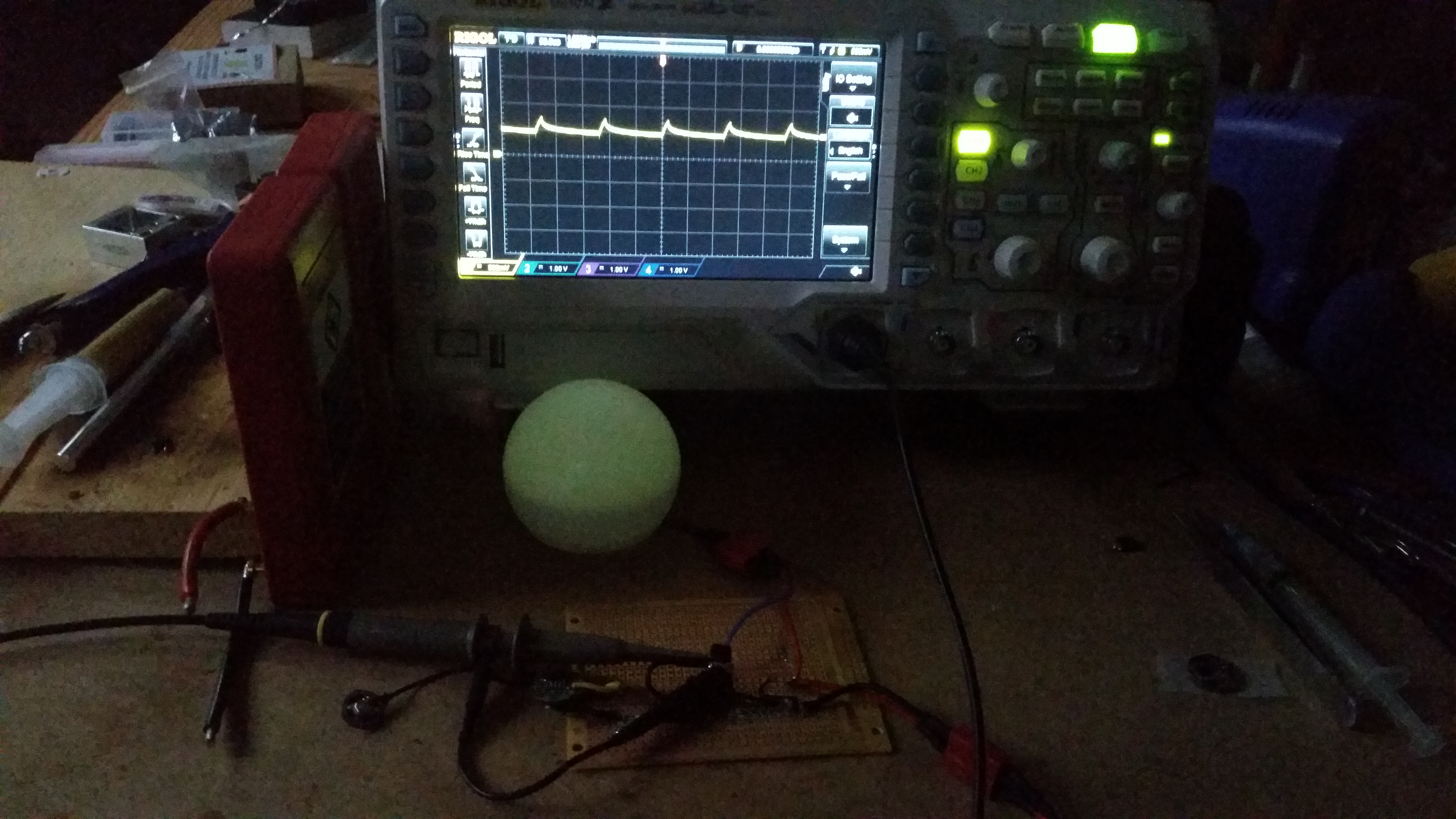
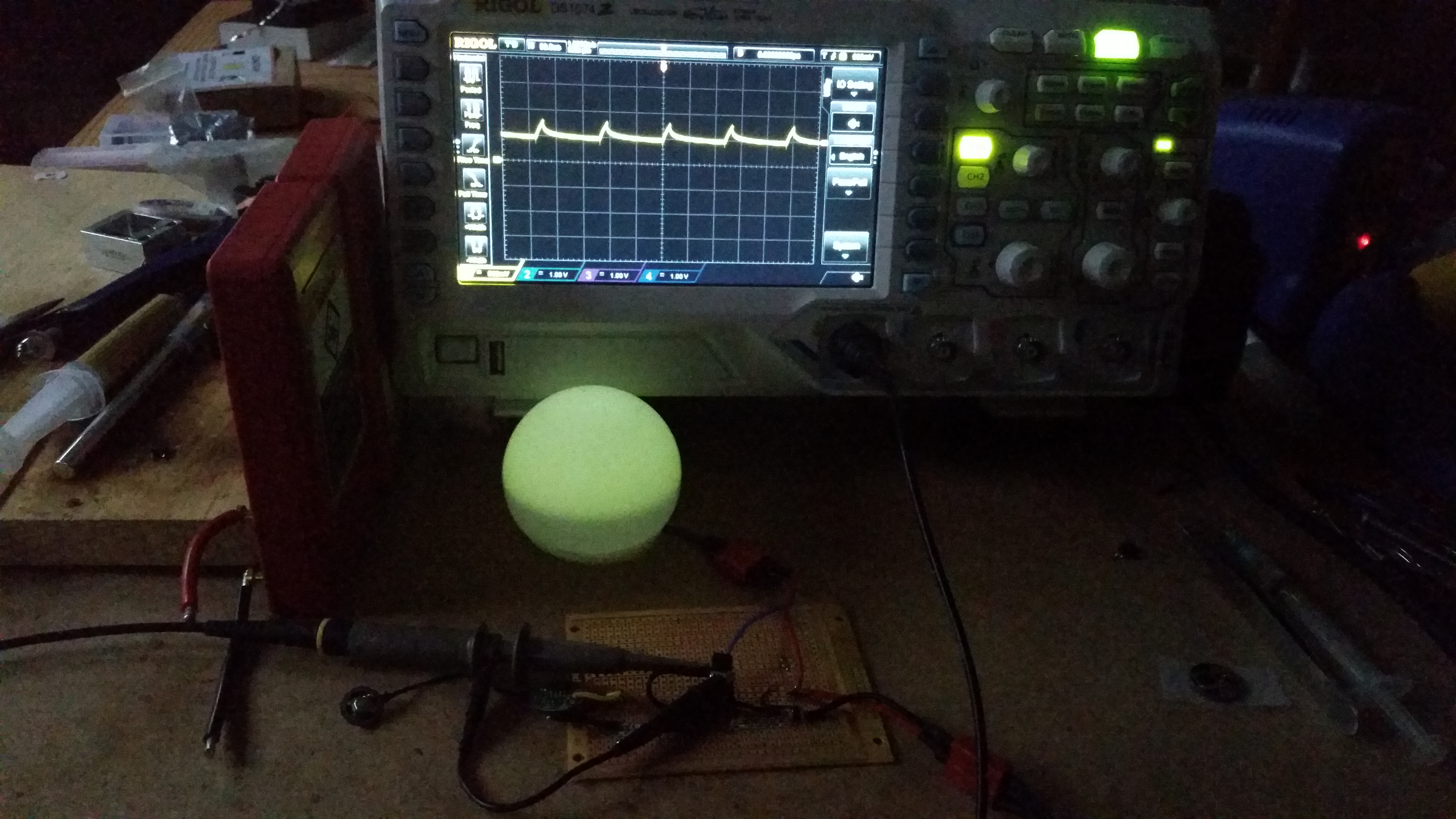
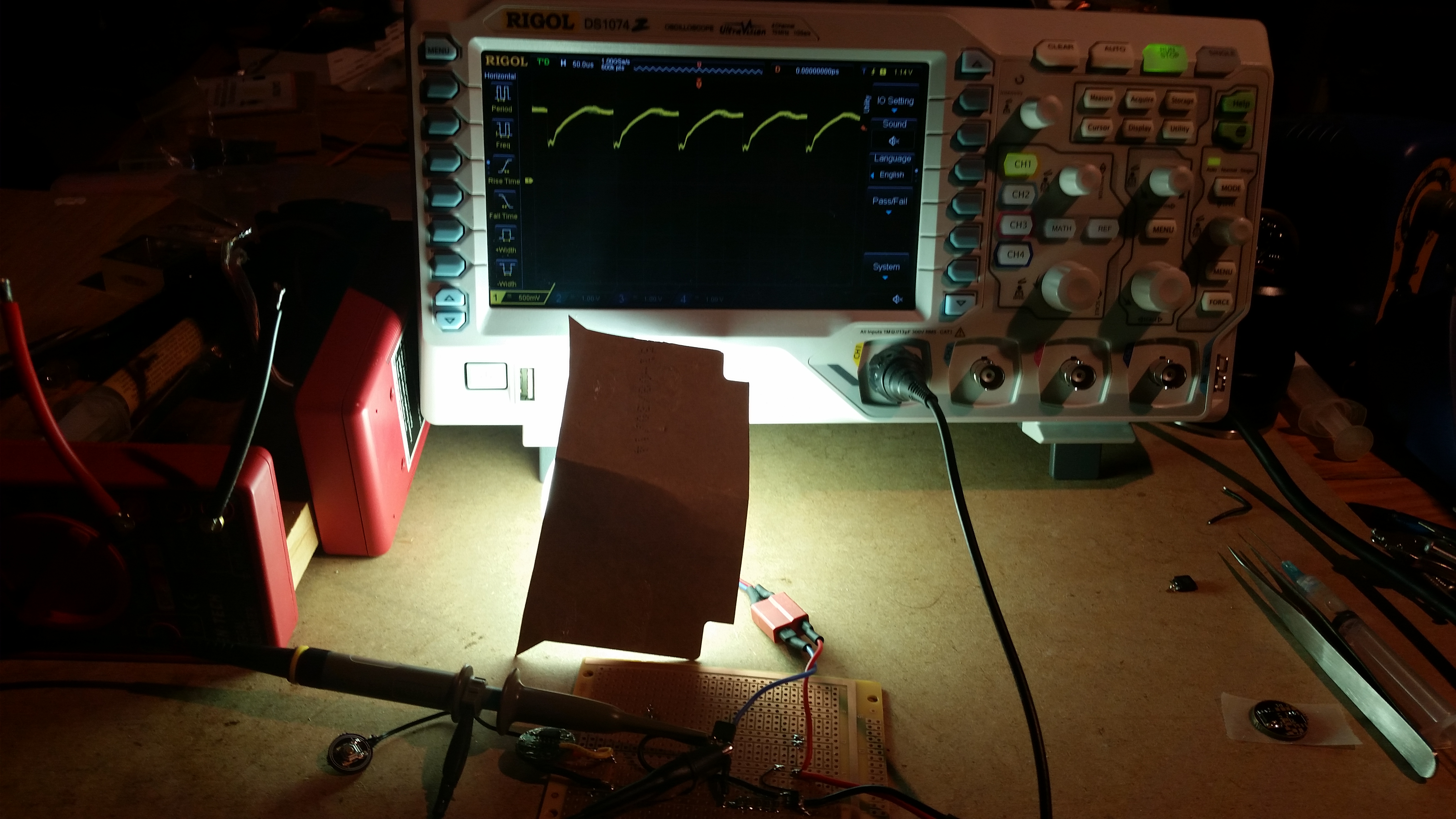
As you can see, there is a lot of noise on that. Zooming in, we see the nature of the noise.
I think that the output waveform looks very agreeable. Note that the pictures show an output of maybe 2.4v! While this may not be the smoothest output ever, it’s free of the normal “off” pulses we see from a 7135 driver. I think that this driver will be much more efficient than I realized at low levels. Note that in the most zoomed in image, voltage never drops below 1.7v and does not exceed 3v.
Nice work Wight, are you aiming to be the most prolific driver creator on BLF?
Is the 7136 similar to the 7135, just without the internal mosfet? If so, can you spare one of these devices? The only suppliers I can find of 7136 are on Aliexpress, never used them dont seem to like PPal….


