I have several projects underway but at the moment this one is nearest to completion. Having acquired over the past year some very nice bits I was looking at ways to combine them and settled on this:
Quad Nichia 219B
Dtche copper quad mcpcb
Led4power LD-1 driver
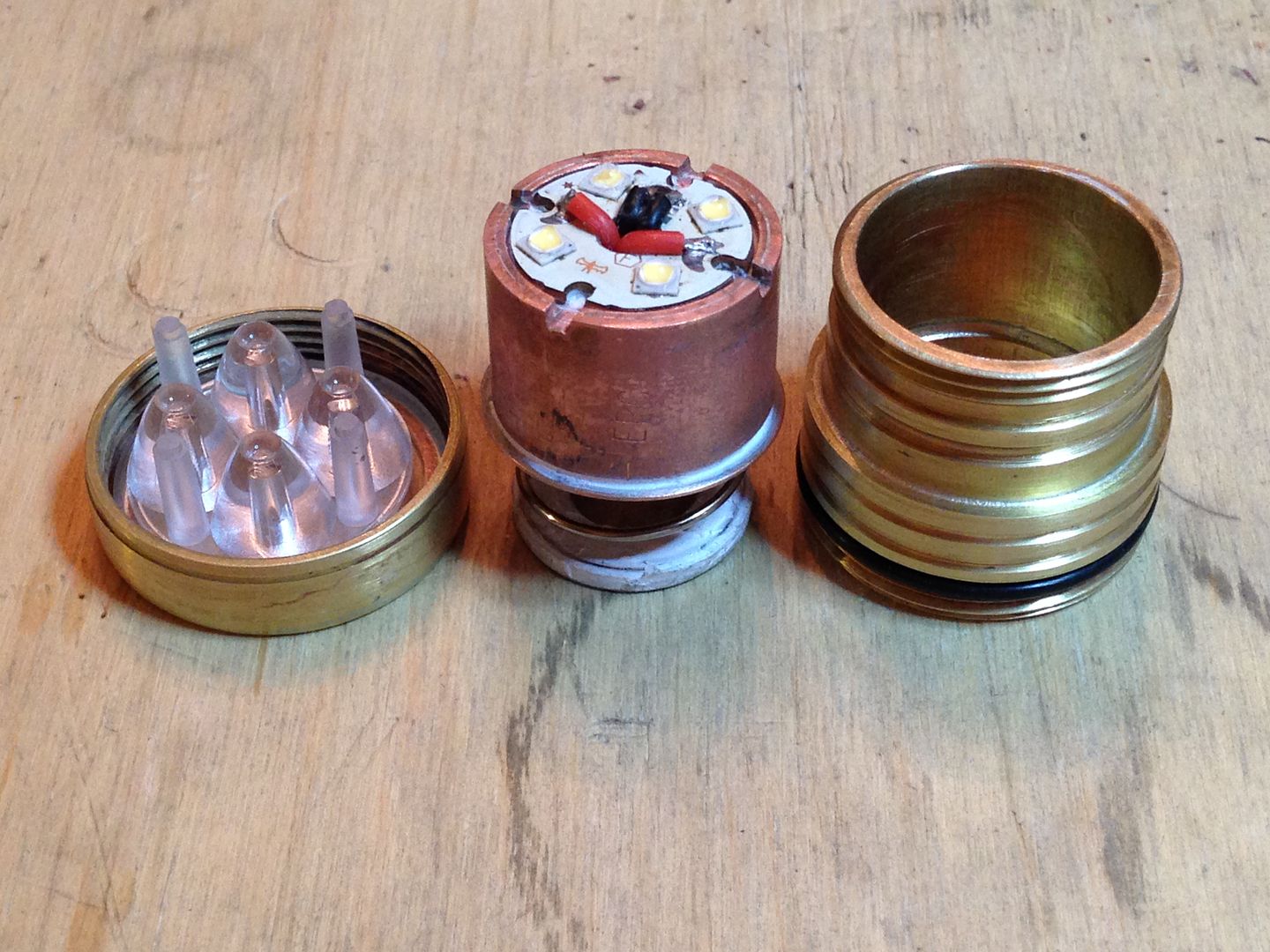
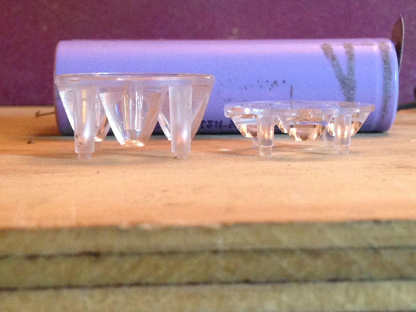
Khatod PL115125 25mm quad optic
Threaded brass plumbing parts
Not nearly enough pics
In an absolute sense I’m still pretty weak with my brazing skills but there’s been steady if painfully slow improvement. I make a bezel by brazing sheet to a threaded collar and cutting out the center. The center is saved as discs of various sizes are always handy to have. The rest of the head is part of a faucet handle base cut down, reamed out, and mated to some female threads from a sink tail piece. The battery tube is the matching male threads butted to a resized section of 1 1/4” brass pipe. The really fun part is the copper heat sink and pill. The LEDs are near the edge of a quad board and this being a dive light I was less interested in a mass of copper than in having adequate surface contact between the head and the sink so with that in mind I made the sink hollow but long with only about 2mm of copper under the star where the LEDs sit. I used copper repair sleeve that fits over 3/4” copper pipe for the outer most tube layer with just a short section above and below to sandwich the led shelf. This left ~ 10 mm inside the sink for the pill and still a ~6 mm hollow space for the wires.
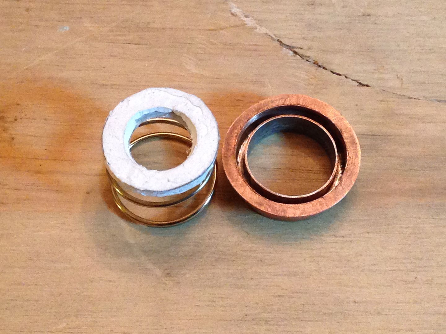
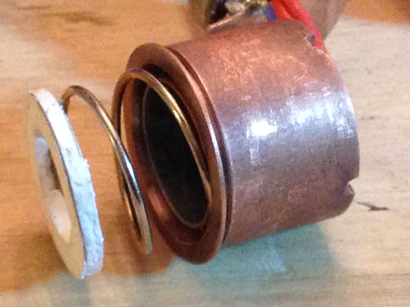
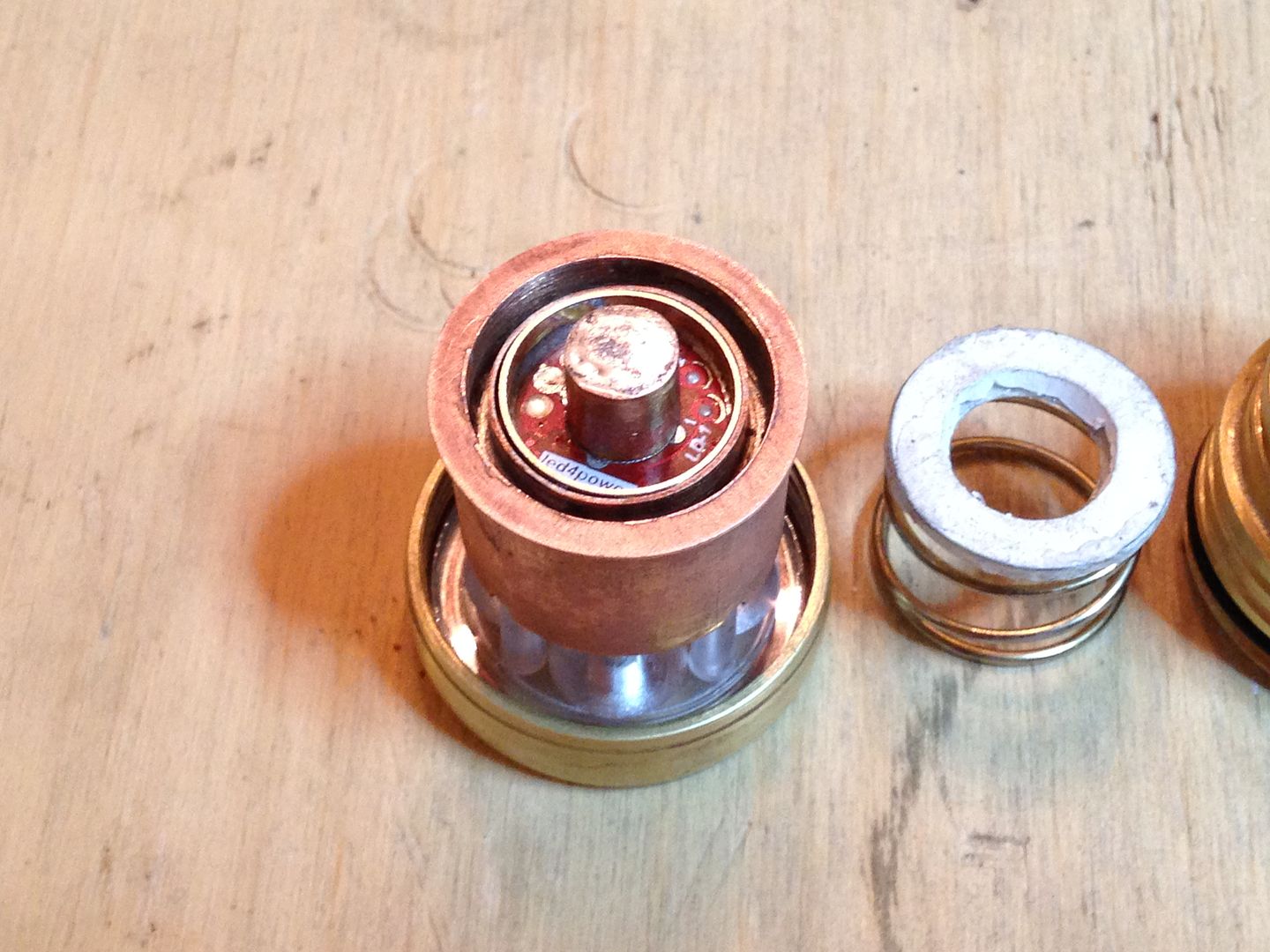
Somewhere I had the idea of using a p60 spring and my first pill making attempt was not successful. I tried to make a well for the spring out of 3/4” pipe, sheet copper, and 1/2” repair coupling(5/8”OD) but the space between the two was too snug and the spring would stick. So instead of pipe I rolled a strip of thinner sheet stock into a tube and did the same thing for the inner wall of the well and used a ring of #14 solid copper wire to space the two concentrically when I brazed them to a copper sheet. After trimming the excess I had something like a hollow donut just the right size for the spring which was a slip fit into the sink. Adding and tinning a lip like a hat brim completed the pill and it was time for the driver.
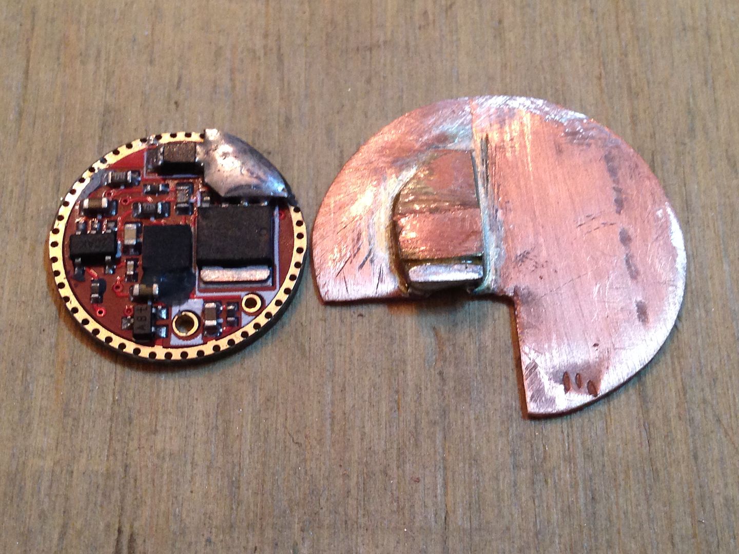
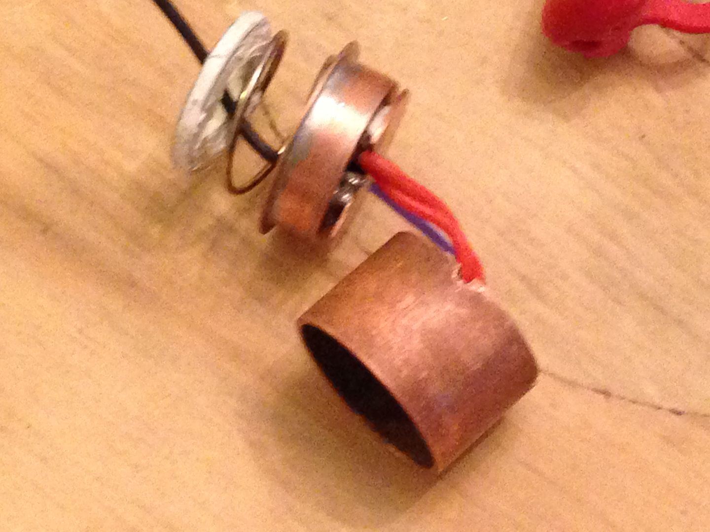
Many of us purchased the LD-1 driver and know that it’s not reccomended for use with paralleled LEDs due to the lower Vf of shared current but still fairly high power through the FET on medium modes unless one uses a daughter board to move the heat generated by the FET away from the mcu. Me being me, I made a copper disc with a tab that solders to the drain of the FET and the led- wires but is otherwise electrically isolated. Since the FET also has 3 ground pins I also soldered a small bit of copper sheet between them and the sense resistors. I had added a second to bump the current up to 10A(~2.5A per led). The copper sheet is bonded to the driver with fujik and also to the pill forming a dielectric layer while still allowing thermal transfer. Before potting the driver/sink disc combo into the pill I tested it in free air and while the disc was hot tab the 2A setting thermal protection did not kick in. Modes measured very close to the .02A, .2A, and 2A programmed while high measured 9A from the first charge cycle of a KK 5000mAhr 26700. Rather than a doing a spring mod I chose to make a copper pillar from sheet copper and 5/16” tubing. This kept me set the contact point with the battery just before full compression of the p60 spring. This spring carries no current but along with the rest of the pill sits at ground potential and cannot be allowed to contact the large B+ of the 26700 cell so I found a convenient plastic washer and bonded that to the spring with fujik.
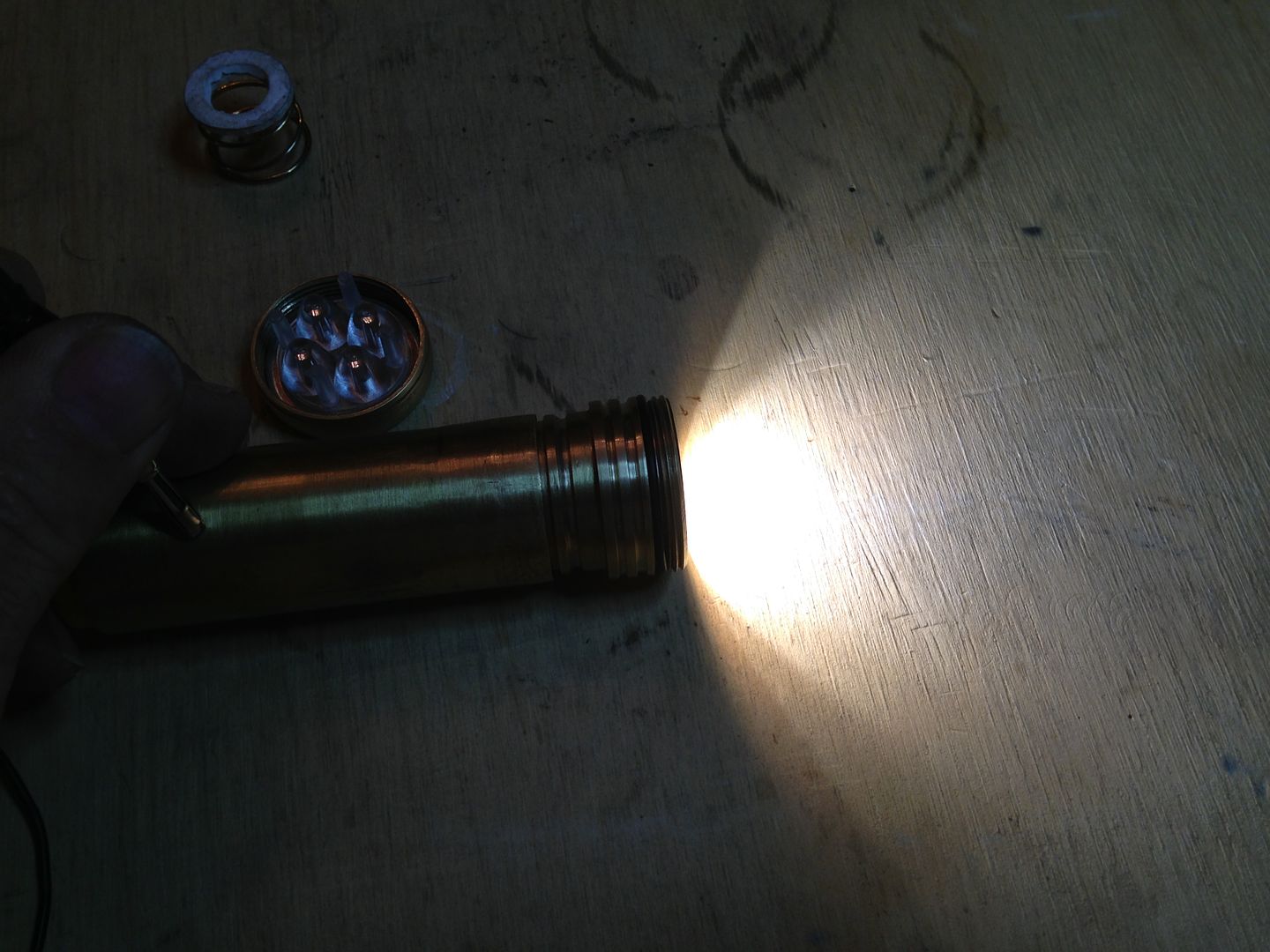
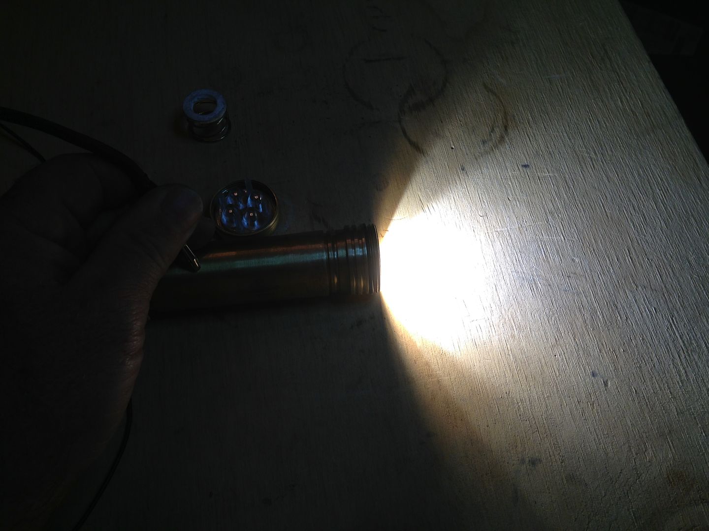
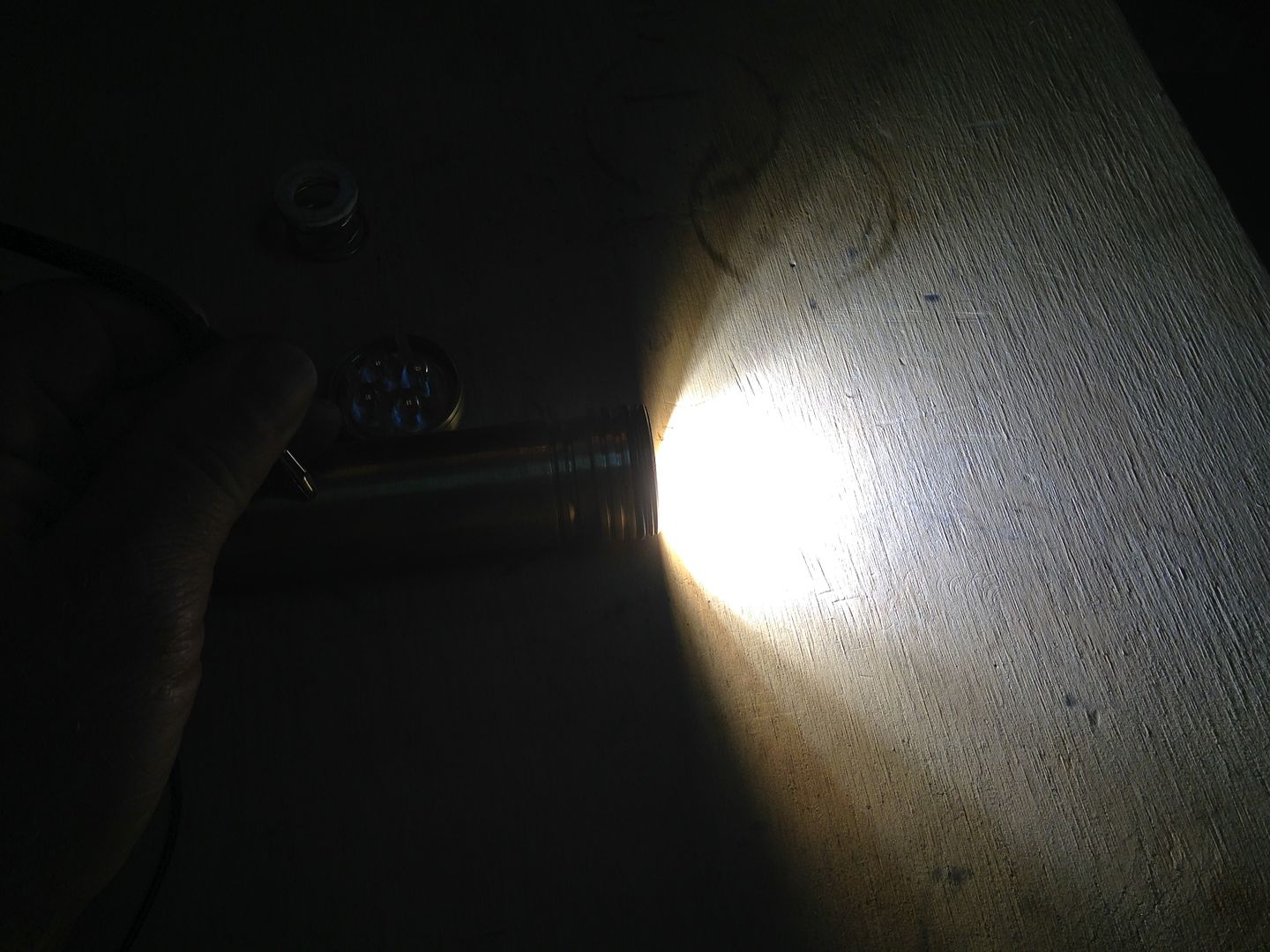
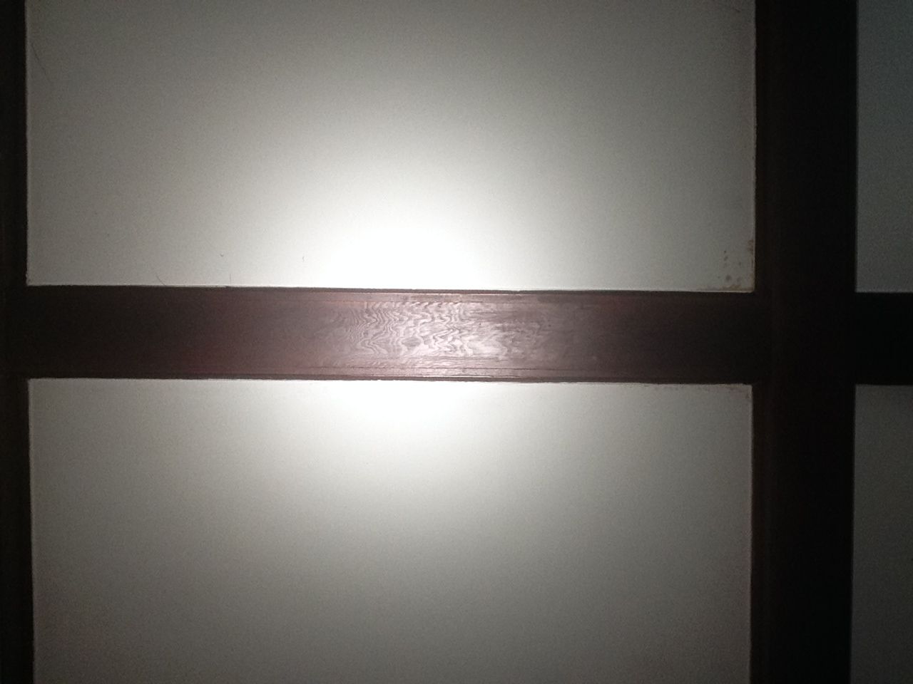
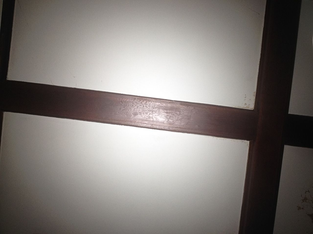
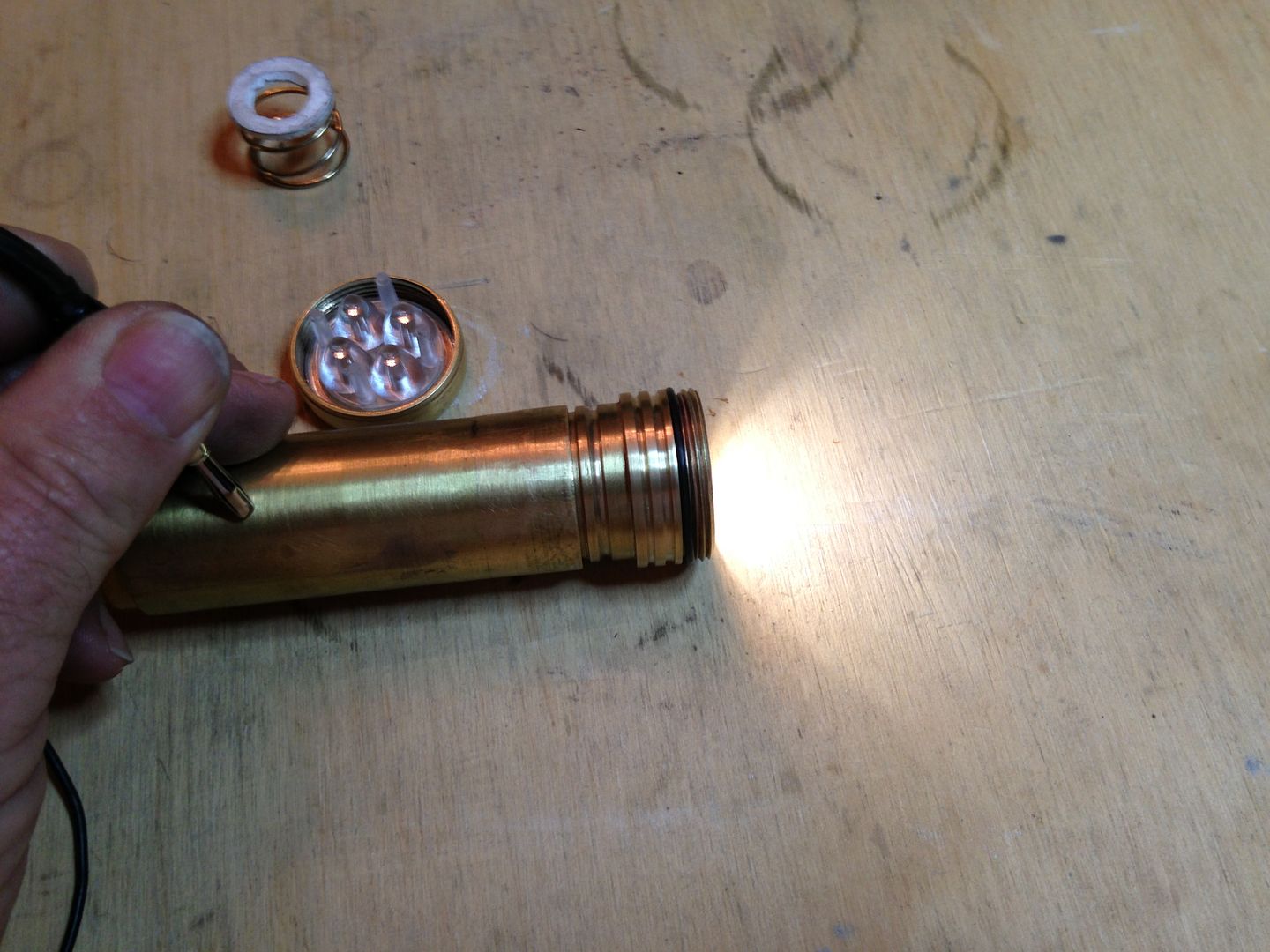
Here it is on low. You can see the p60 spring above. It’s not installed because the tube has no bottom so the threads can’t be used to compress it. Easier to just hold a piece of wire to B- and the case with one hand while I shoot with the other.
It’s a bit late now and the iPad charge is low so I’ll add some more pics tomorrow.
 I'd suggest a mystery novel as I think you know what this dumb Moose is on about. I still think you have a bit of closet plumber inside you somewhere.