Be-Seen Bike Light Build

The ultimate Be-Seen bicycle light build - P60 drop-in for 28mm aspheric lens.

NOTICE: ...this is NOT for you thrower fans; it is NOT for those who like absolute brightness; this mod IS for those who want a nice bike light with a wide dispersion beam that won't blind the very people you want to see you. These are front or rear Be-Seen lights; not specifically lights for seeing, although this does put out good light. This is a fixed unfocused solution with a wide variety of modes specific for your needs of cyclists that want to be seen from wide angles.

History: ... I've been using UltraOK 18650 blinky zoom lights for the past 3 years to be seen on my bike. I have had very positive comments about the lights, and the behavior of the cars in my vicinity has been more favorable than I could have ever expected.

Choices: ...a lot of time has been spent deciding how to get longer runtimes; lower flash rates; an appropriate emitter for the build; and the appropriate light output. I chose the XM-L emitter for the low Vf requirement at lower currents. The XM-L can run at 1A down to under 3V; the driver choice was the 16-mode NANJG 101-AK driver because of the "police" and 1hz strobes. There are other nice modes here but these are fairly unique and easy to dial out if you don't want them. I also choose a 1A drive current to the XM-L as this is sufficient for the purpose of this light. This is also the current the UltraOK zoomies run at into XR-E Q5 emitters. This should make this light a bit brighter than the Q5's but provide consistent light output throughout the battery life.

The host I chose was the UltraFire 504B due to the 28mm lens and the robust, and replaceable tail switch. This is also a P60 host which was probably the easiest module to modify for my purposes. The 28mm aspheric lens came from Deal Extreme and the red film for the tail light version came from ebay. This essay is about the P60 drop-in build since any P60 host can be converted if you have the aspheric lens to fit it.

You have to admit, this is an impressive light:

Silver UltraFire 504B w/ red aspheric

1st I needed to know where to place the emitter. The actual position of the yellow stuff in relation to the lens. Turns out that the physical center of the 28mm optic is only about 5mm from the flat surface of the lens; not where one would think when you get an actual optical focus which is close the where the P60 would normally put the emitter. A previous experiment had given me some insight to the matter. But this CAD work was an eye-opening exercise. In this case, the die is at the physical center of the lens' sphere.

CAD study of the optics

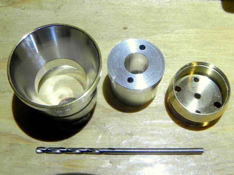
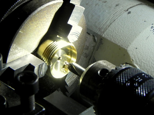
Some machine work was required to the pill, the reflector, and a custom pedestal for the emitter. The pill was machined with a vent hole; The driver pocket was deepened for the NANJG drivers which are 1.6mm thick; the emitter "floor" was smoothed and flattened; and the ID of the emitter pocket was opened up significantly.

Pill being machined on the mini-lathe

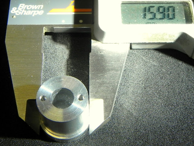
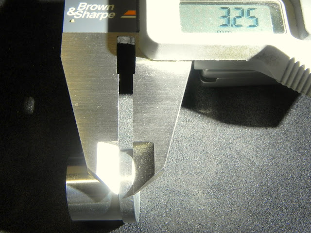
An old smooth reflector was machined out to accept the pedestal, and the pedestal was machined from aluminum to drop-in in the pill and held by the reflector. You will see a shoulder on the pedestal and a pair of holes through the pedestal all the way through the pill. These holes are for the wires. The emitter side of the holes were also tapped to #2-56 so the emitter could be held for gluing. The hole in the center is there simply because that was what I found at ACE h/w. A future post will detail the pedestal for those wanting to duplicate the work.

View 1 of the modified parts

View 2 of the modified parts

It took me a while to figure this out but I decided that gluing the parts with Arctic Silver epoxy was the best way to go for holding the parts. I glued the pedestal in the pill aligning it with the drill bit and clamping the pedestal with the modified reflector.

Pedestal being glued into the pill

Making sure the wire holes lined up with the pill

At the same time, the emitter was glued to the pedestal being very careful not to get glue in the threads. This is the reason for the earlier breather hole in the pill so there was no trapped air space that would pop off the emitter.

The emitter with glue sitting on the pedestal

I used a Mylar washer with a pair of holes and some brass #2-56 screws to clamp the emitter star down to the pedestal while the thermal epoxy cured.

Emitter clamped to pedestal

Once the thermal epoxy cured, the Mylar washer and the screws are removed.

Emitter epoxied to pedestal

I placed the aspheric lens on the pill to check the ~1mm clearance. The 504B host has an ~1.8mm lip for a total of around 3mm clearance to the dome of the XM-L.

Emitter through aspheric lens

Once again I choose to use solid core wire; 22awg. I also opted for the Teflon coating that I stripped off the Illumination Supply 24awg stranded wire. This was a tight fit, but the high temperature that Teflon can take when soldering the wire made the effort well worth it. I wish I had some red and black, but this works good.

22awg solid wire and salvaged Teflon sleeves

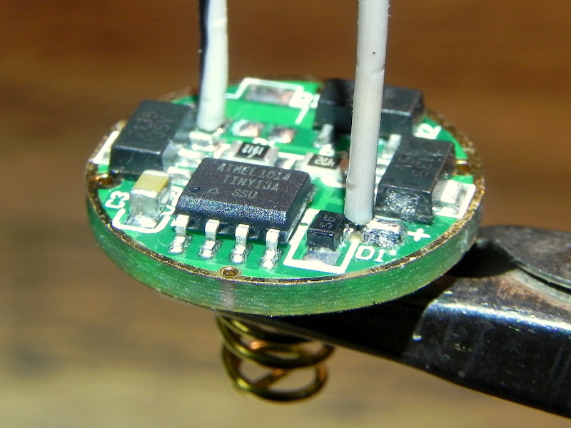
The new NANJG 101-AK driver was received from KaiDomain in record time. This driver looks as good as any of the previous drivers I've received on this brand. I had little concern about DOA so I just went for the build.

NANJG driver and wires

A quick break and grind of the tabs on the driver made it ready to test fit into the pill. These often come a bit large but I had already accounted for this when machining the pill. Then a small twist at the end of the wire and the wires were quickly soldered to the driver. The insulation slid down to the solder joint easily. The spring was also soldered to the driver.

Wires and spring soldered to the driver

The insulation was trimmed to about 1/8" past the emitter star. The copper tails were left long. The driver was dropped in place making sure the driver "+" was to the "+" side of the emitter! ...and the driver was soldered to the pill with the aid of some extra wire to bridge the gap.

Driver soldered to pill

Now it is time to check the business side of the build. The insulation is well past the emitter star...

Emitter w/ wires ready for prep

Wires trimmed and formed ready to solder...

Wires dressed for soldering

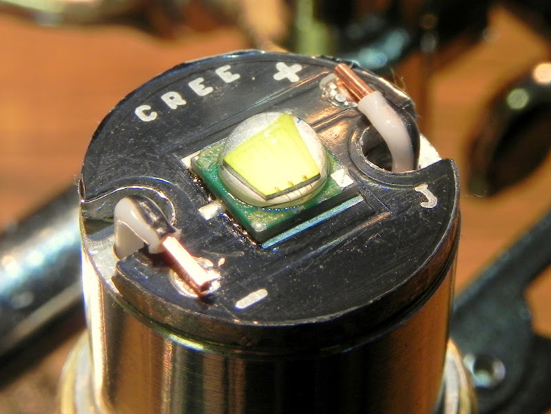
Wires soldered, flux cleaned, ...fingers crossed.

Wires soldered to emitter

Moment of truth. Add reflector, large spring and check the emitter with the diode check function of the DVM; check the battery connections for shorts with the ohmmeter... all good.

Pedestal P60

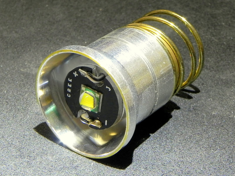
Things look pretty funny through an aspheric lens. The emitter looks like it is as deep as a P60 with a normal lens. It really is only 3mm below the lens. The emitter itself looks about 5 times as tall... and everything is bigger. The lens has the red Rubylith in place making this an awesome red flooder.

"pulled" emitter

"zoom!"

...and a parting shot.

Stay tuned for the details of the pedestal and pill/reflector mod.

I have a very poor selection of raw materials, but an hour of floating around the Ace h/w store yielded an aluminum cable collar of the right OD and length. It has a hole in the center but I wasn't to worried about the reduced bulk material. It would have enough interface to get heat from the star to the pill and the reflector. So I proceeded.

Be sure you know where you want the emitter in relation to the lens. The pedestal's barrel length can be adjusted to what-ever length you want for your emitter. Also check the lens position in the host in relation to the reflector. In this case, there is a lip in the 504B almost 2mm thick which has to be added to the results. This design is for placing the dome of the XM-L emitter at about 3mm from the lens (so it doesn't melt the rubylith). Thermal epoxy and very flat interface surfaces makes sure to draw away the heat from the under driven XM-L which should stay plenty cool for the task at hand. If you want a full 10 watts output, you will have to work a little harder at making this cool better. Some minor tweaks can accomplish this easily.

You see some tight fit interfaces and very flat surfaces including machining the pill face where the emitter normally goes. Clearances can be modified at will. This is just an example fof how to get there from here. The idea is to capture the pedestal with the reflector; the reflector is replaceable; the emitter is going to need to be epoxied or glued with a very reliable glue. Tapping the pedestal is optional but recommended if no other clamping method is available. Above all, be careful of the emitter dome once the emitter is glued to the pedestal. I used the reflector to avoid "accidents". The pedestal was glued to the pill to make sure the wires cannot get sheared when replacing the reflector.

Again, these are the mod'd parts:

Overall length: 14.8mm

Reduced barrel length: 11.52mm - this is the depth of the emitter in the reflector.

Reduced barrel diameter: 15.9mm - just match this to the reflector. More material will help thermal characteristics.

Flange diameter: 17.35mm - this follows the pocket in the pill. The pill could be "leveled" for maximum diameter/material.

Flange thickness: 3.25mm (REF) - This is just slightly deeper than the pill pocket.

Wire hole spacing: 12mm (16mm star) - tapped holes: #2-56 drill size:#50

Pill diameter (pedestal side): 17.34mm - should be 17.4mm enough to tightly fit the pedestal. Watch for tool radii!

Vent hole in pill needed if the pedestal is hollow. - only needed if you use a hollow pedestal.

Through holes for wires: Also notice the deepening and over-sizing of the driver pocket

Bore diameter in reflector: 16.03mm - there is no real limit here if you epoxy the pedestal into the pill. The reflector's thread ID is the real limit.

I hope this was at least an interesting read even if you never really care to do this. Enjoy your DIY projects and post 'em up. You never know who will be interested.

Excellent built. Wish I have your skill and patience.

Thanks! This is a culmination of so much information I've learned from the great people of this forum. Without BLF, I would have never got to this point. So it is all of you that I owe thanks too. H)

*RESPECT*

Love the clean finish, I am VERY impressed by what you have achieve, and the attention to detail. Makes me want to do some more custom work!

Well done!

Wow .

Just ......Wow .

Excellent work and how-to complete with great pictures .

The culmination of a lot of thought and hard work .

Very impressive , thanks for sharing .

WOW man, I didn't know you had such skills with the power tools, The electronics i knew you had those skills tho. :) Plus you put alot of thought and science into your design, Id just JB weld a copper tube to a reflector and glue it into place. Man thats sad.....

Now i just gotta start begging you to make me some heavy duty P60 slugs from copper, Or help me find a $50 lathe! lol But then again ill need new hosts that are more heavy duty to disperse all that absorbed heat. Man this hobby is just one big series of upgrading until what you have left is just a handmade light.

Well it would be if i had the tools and skills anyhow. Luckily im limited too electronics.

Thanks again guys. This has been a long time coming. My earlier work with this aspheric proves out pretty well. With the light 3 feet from the wall, I get a beam just over a yard wide. This confirms the expected 50 degree well dispersed cone angle I was expecting. With the spill to the edges, it is an easy 60 degree cone. I removed the red film for the following shots.

Here are some beam shots: XM-L T6 LCK LED XMLAWT-00-000-0000T6051 WHITE

1/60-second exposure, f2.8, 36" to the wall:

Control

Low: ~50ma

Med: ~300ma

Hi: ~1A

Video of the modes to follow.

Very impressive. I sure wish I had your skills. :)

Let's see if I can embed the vid. Warning, it is seriously boring!

Well, what do you know... 17-modes! :|

Group 1: Low/Medium/High = 3 modes

Group 2: Low/Medium/High/Fast Strobe/Police Strobe/0.33Hz Flash/1 Hz Flash/10 Second Beacon/SOS = 9 modes

Group 3: Low/Medium/High/Fast Strobe/SOS = 5 modes

3+9+5 = 17 modes.

Yes, this is exactly the same as the driver I got from DX

Do you have a picture of your lathe? I was looking at the chuck and I noticed some marks on the jaws (oops?) and then I realised that the lathe was a cutie...

Hahaha... a lathe without marks is an unused lathe 0:)

This is a Emco Unimat 3 that my dad got me several hobbies ago.

Very nice work!

I think this is worth posting.

Why I choose the XM-L over the XP-G. This treatise only applies to a very under-driven XM-L using 3x AMC7135 for 1050ma to the emitter. This seems to be the "sweet spot" for the XM-L driven by 1x Li-Ion cell.

From Cree's datasheets, it is very apparent that the XM-L will stay in regulation a lot longer than the XP-G in single cell Li-Ion applications. We must remember to account for the voltage drop across the AMC7135 devices but overall, the XM-L will remain at a constant brightness almost until the NANJG driver hits the low voltage alarm (nice feature). Depending on the 1A curve of your particular battery, the XP-G could start dimming half way through the charge. Driver input voltage for the AMC7135 driver will be around 3.1V when the emitter sees 3V based on a 1050ma draw. At 3.1V, a cell with a sharp knee will dump rather quickly. The protection circuit kicks in at about 2.9V.

This is not to say that the XP-G doesn't have a place in the flashlight realm, but it is probably served best with a buck driver with 2 or more cells, or with a drivers that will actually maintain constant current and boost the voltage of a low charge on a single cell. I haven't found that driver yet. With the quality and the simplicity of the NANJG drivers available for single Li-Ion lights, it is hard to get excited about qualifying more drivers.

Other great features of the NANJG drivers: Memory; groups; and they maintain their mode through a single transient (<- this is an important feature!); Adaptability to higher or lower output currents.

Red data is the XM-L data; the solid blue is XP-G data while in regulation; the dotted blue is the XP-G when the emitter is at 3V where the XM-L is still in regulation.

Nice work!

Such a TINY lathe!! Love it!! Something that doesn't take an hour to clean up! ITS SOO CUTE!!! OMG!

My late grandfather bought a Myford Super 7 for his live steam hobby, and I now use it for things here and there. A chinese lathe can be bought for 1/10 the cost of the british lathe, but this old british lathe still out cuts the chinese lathes simply due to outright quality. Not many more features than yours, but it does the job!

I finally went through a runtime test.

With Rev Jim's 2350mah Panasonic cells, I got 11+ hours of runtime in the police strobe mode.

The brightness remained completely constant until it went into the driver's alarm mode (low output blinking)

That is HUGE.

Interesting. Makes me want to own a lathe. Did some research and found out that i have to learn a ton before fiddling and finding the right one. It seems a novice selflearning wannabe lathe expert can hurt himself pretty easily and pretty hard. In the end i will not bother with, and go the usual free shipping route even if i dont't get what i want from the usual suspects. DIY parts are getting annoying. Always the same stuff. If occasionally some1 gets something new 90% of the time is junk or heavily overpriced.

I would really love to do my own flashlights. Even a few for sale. Basiacally, good drivers, optics, sweet tolerances, reliability and a strong aesthetic factor.

I like:

Not exactly my style but you get the idea.

Thanks for sharing! This makes me wish I had some more time to use my lathe! (and learn how to use it