You should consider ditching the zener and using a LM2936 instead in a SOT223 package. Will regulate to a very nice 5 volts and have very, very low parasitic drain. Can handle up to 40 volts input. It has built in reverse polarity protection.
It needs a resistor in series with a capacitor going to ground on the output pin. Your board's existing cap should cover the need for an input cap.
I have these on the way. I would be happy to test such a board if you designed it.
Does it have an advantage in non-eswitch applications?
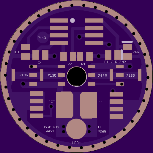
Frankly, I don’t know enough to start incorporating other components, I basically just physically rearrange existing circuits. If I can find a footprint, and you can show me how to connect it, I’d be happy to do the work in Eagle. Feel free to shoot me a PM with a simple diagram if you have one.
The LM2936 does provided much more benefit to momentary switch lights. Of course, a momentary switch could be connected to the OTC pads on your board.
In a clickie light, it should have much less voltage drop out during operation. How much more voltage/current that would make available to the emitter, I don't know. The longer the light is on, the more important the loss would be. In a light that someone is trying to eliminate every little loss (e.g. resistance mods, etc), it will be considered a benefit.
The MCU would also get much more consistent voltage. I've been very impressed with how solid it's voltage output is.
I don't have Eagle on this computer. I'll PM you the info I have so far when I get on my other PC.