First I have to apologise to led4power for posting this so late, he has send two of his new drivers to me for review already a month ago, which I really appreciate because I do not see myself as a connaisseur of custom drivers and do not have the electronical knowledge and equipment to do quality testing like HKJ does. I received them a full month ago and it took until now to write a post about it. Reason is that I did have numerous little time-slots to chat in the forum but the past month there has been hardly any serious time (like hours on end) for hands-on hobbying and writing proper posts.
In this post I write down my impression and some observations on the LD3 and a few measurements.
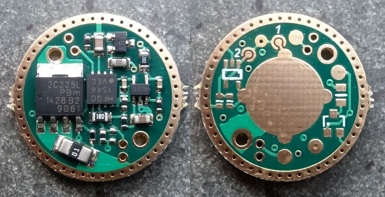
I received the drivers together with the parts to solder on the driver for moonlight, plus the wires and some NTC-resistors to build the external temperature sensor. The driver hardware is (as far as I know) exactly the same as the LD2 driver, but the firmware is radically different. So this impression will for the greater part not be a hardware test because that is essentially not different from the LD2 that is reviewed and tested before on BLF.
Because of a communication problem with led4power I initially was under the impression that the LD3, like the LD2, was basically an e-switch driver with an added simple clicky-switch functionality, so I started a build into the Roche F6 flashlight (that was gifted to me some time ago by nicolaas). During the build I started testing the functionality and could not get the e-switch to work on this driver. A quick question to led4power resolved the problem: a major difference between LD2 and LD3 is that the LD3 does not work with an e-switch and is clicky-switch only (so at least I proved that!  ).
).
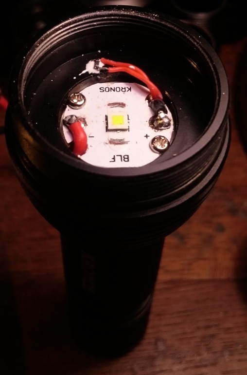
So clicky-switch it was to be and actually I'm happy about that, clicky-switch builds are way easier than e-switch builds, it makes this driver including its many features suitable for many more flashlights. My BLF-X6 flashlight was still unmodded and I had a nice warm white XP-L Hi still in my emitter-stash, this should be a representative test combination and would leave me with a fine flashlight when the test was over.
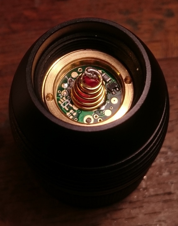
Here's a picture of the driver in place. I bypassed the tail spring too. Later I added a bleeder resistor which is not in this picture yet.
Next to the ledboard I glued the NTC-resistor with Arctic Alumina Adhesive to the inside of the head.
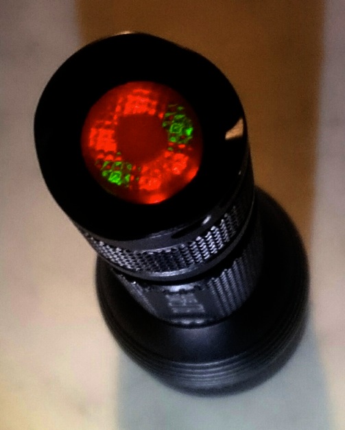
After assembly and making sure that the flashlight worked as it should, I tried out a lighted tail. For every new combination of host, led and driver, the lighted tail must first be tried out, resistor values of tail and bleeder adjusted, current and light output fine-tuned and checked every time if the UI is still intact. For some drivers I never got the lighted tail to work at all without messing up the user interface completely. I was delighted to find out that several very usable combinations of values can be build in combination with the LD3; some influence on the UI-timing is present but I ended with the following values that left the UI fully intact:
bleeder resistor: 3.9 kOhm
6-led dumb tail ring resistor values. 2 pairs of red 0603 leds: 3.3 kOhm resp., 1 pair of green 0603 leds: 1 kOhm (0603 leds were from Fasttech)
The current-drain from the lighted tailcap when the light is switched off is 0.562 mA, so it takes over 7 months for a 3000mAh battery to drain. The brightness of the lighted tail is perfect: dim in daylight, well visible in the dark.
So now for the user interface. Led4power told me that he spent a significant part of his free time this summer on the new firmware and I must say that it shows! Usually a comprehensive user interface is wasted on me, give me a simple low-med-high without memory and well spaced modes and I'm a happy camper, but while in this driver just about everything is user configurable ( ), the configuration interface is so well thought-out, clear and intuitive (confirmation of what happens is done with numbers of flashes and two different low outputs as indicator during the setting session) that I found it a pleasure to use. I even found myself checking out many different settings with ease while usually I do not bother optimising settings when configuration is complicated. Here's led4power's chart of the different settings (I hope that he is ok with me reproducing the chart from his preliminary datasheet) : while it looks very extensive, it is dead easy to do all settings in one quick session, and I could even create my old favourite low-med-high no memory :-D :
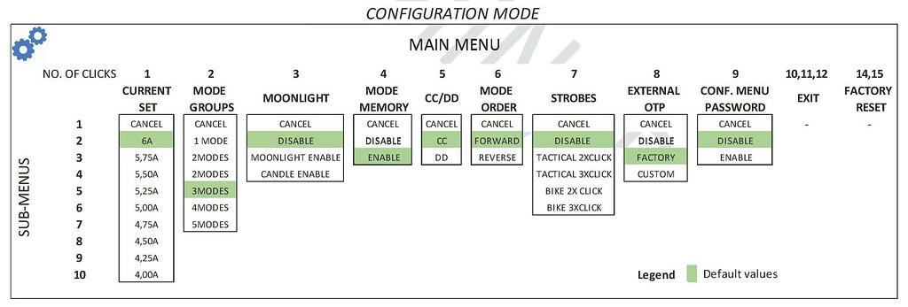
I must confess that I did not test a crucial new feature: this driver is set to a regulated maximal current by hardware, but this can be influenced via the user interface in two ways:
1) the maximum regulated current can be adjusted down to 66% of the default setting (so a 6A driver can in steps be adjusted down to 4A, 9A driver to 6A etc.) (menu 1)
2) instead of a regulated highest mode you can choose for direct drive (menu 5)
Led4power asked me to check the active state current of the MCU because it is supposed to be quite low in this driver while in some drivers the current loss by the MCU can be higher than the current through the led in moon setting, significantly reducing the runtime in moon. So I did that, and (with some values assumed) found the active state current of the MCU to be about 1.4 mA (while 1.5mA according to the datasheet). Btw, I used a moonlight resistor of 680 Ohm, that gave a moonlight current of 2.4mA (0.72lm), and the added 3.9 kOhm bleeder resistor causes a loss of about 1.1mA. So at moon setting this flashlight draws combined 4.9mA (measured), that is about a month runtime on a good battery.
I did a quick comparison with a flashlight with dedomed XM-L2 and BLF-A6 driver on moon setting: that flashlight draws 3.52 mA for 0.49 lumen. with some quick/dirty assumptions that all else is the same this suggests an active state current of the Attiny in the BLF-A6 below 2mA as well.
Last what I did was a runtime test on a freshly charged Samsung 30Q with the driver set to direct drive, while measuring the light output and head temperature simultaniously, to test the overtemperature protection that this driver has build-in. I could have done that before on the LD2 driver, but did not do it at the time. This is how the set-up looked like:
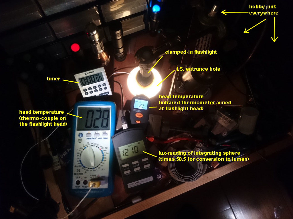
I measured the head temperature in two ways because I did not trust the very cheap infrared thermometer. The themo-couple/multimeter combination I had calibrated to be within 1 degC. The infraredthermometer did very well it appeared, mostly within 1 degrees of the thermocouple :-) (even though in this picture at the very beginnig of the test they are 6 degrees apart, immediately during heating up they matched up)
Not being able to write down three readings every 20 seconds, I made a video with my phone of the test, uploaded it to youtube (my phone-screen is too small to do the read-out) and wrote down the numbers while playing the video back. Unfortunately not only decided my phone to stop filming every now and then, also during the upload I seem to have lost two periods of a few minutes. So there's some ugly gaps in the data-set.
Nevertheless, the graph contains enough useful information to draw some conclusions :-) :
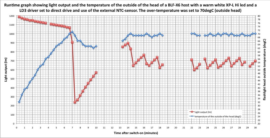
Before the test I set the overtemperature threshold using the configuration menu: I set it when the head temperature reached 70 degC as measured with the infrared thermometer. This is a high temperature: perhaps the led itself is over 100 degC, but it is not hot enough to unsolder stuff, the light seem to survive it well, and 70 degrees is not hot enough to burn stuff when the light is accidentally switched-on on your bag or pocket.
As you can see, the driver manages to keep the temperature effectively around the user-set 70 degrees, the safety feature works as it should! Perhaps the only small imperfection is that in this particular configuration with X6 host, XP-L Hi led and this position of the NTC-resistor, the first step-down to 200 lumen could be less harsh , I figure with a stepdown to 400 lumen, the temperature would still have stayed under 70 degrees. (But mind that in smaller flashlights this large initial stepdown would be very much needed, I can understand the reasoning for it). The next series of stepdowns were nice and precise, the driver found the correct average output to keep the temperature around the threshold temperature.
Conclusion sofar:
This is again a very good upgrade of the LD series drivers, and with so many nice user configurable options, this is the best thought out user interface (operated with one clicky!) I have seen to date.
Thanks for reading!