This one is came from Yamaha NMAX 155 which is i believe will be same as NMAX 125 version for European market
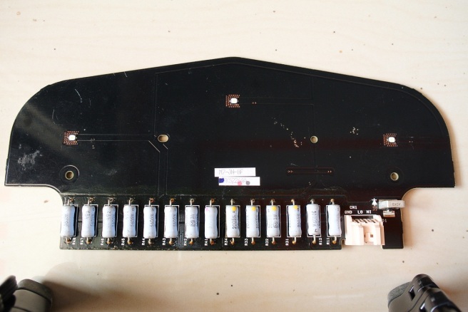
As you can see, those BIG resistor act as “LED Driver” which is ridiculous. Using 3 pieces Osram Oslon Black Flat

And here PCB back view, just some componen like mosfet, capacitor, resistor, etc. Nothing fancy. Made by Koito

PCB itself is about 2 layer pcb with 1.6mm thick and made by “pertinax” ??? Because it feels different than a FR4 material

Trying to do some “reverse engineering” and here full schematic from those PCB.
This circuit is quite simple. First you can see those FET1 for Reverse polarity input protection. ZD1 act as TVS Diode to protect circuit from nasty peak voltage. FET2 act as switch which is work like an SPDT relays selecting between low beam and hgh beam. Those 3 Watt BIG resistor array for current limiter for emitter itself.

This is simplified schematic for easier to understand.

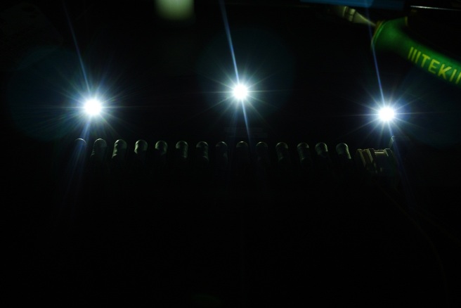
When LO dan GND connected to Battery, 2 emitter at the top will light up since relays still in Normally Close (Off).
Draw about 0.55A when powered from 12.8V power supply. Voltage at the emitter was 5.9V so it translated to 3.2 Watt Output power and dump 3.8 Watt as heat, LOL. That’s the price to be paid for using an ‘Linear Regulator’ like this one, Terrific efficiency numbers.
When HI is connected to +Battery while LO and GND still connected to battery, relays will click and move to NO (Normally Open) positition make third emitter light up.
Draw about 0.64A at 8.8V in High Beam translated to 5.6 Watt output power.
Sorry no output beam since i only got this one as bare pcb.
Thank’s for reading ![]()