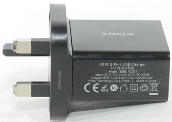
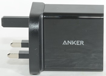
Anker 24W dual port USB charger A2021
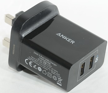
Official specifications:
-
Input: AC 100-240V~0.7A 50-60Hz
-
DC Output: 5V / 4.8A
-
Size: 2.2×2.1×1.1in / 57×54×29mm
-
Weight: 3.4oz / 96g
It is from Amazon.co.uk
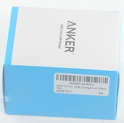
I got it in a card board box, it contained the charger and a piece of plastic, no manual or usb cable.
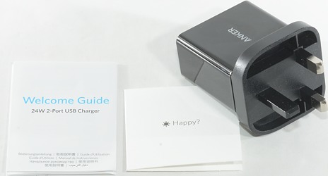
It included the charger and a manual.
Measurements
-
Power consumption when idle is 0.07 watt
-
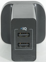
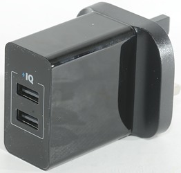
Both usb outputs are auto coding with Apple 2.4A as maximum.
-
Both outputs are in parallel, but with individual port protection.
-
Weight: 82.4g
-
Size: 78 x 49.5 x 47mm
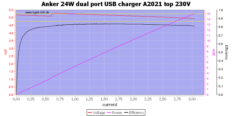
The output can deliver 3A, this is a bit high for a 2.4A port, but acceptable.
The efficiency is good.
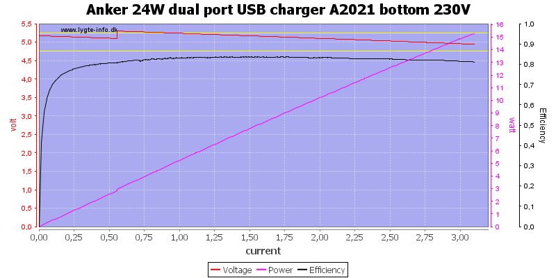
There is minor difference between the current on the two ports.
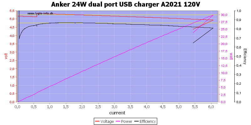
When running both ports in parallel it is possible to draw 6A
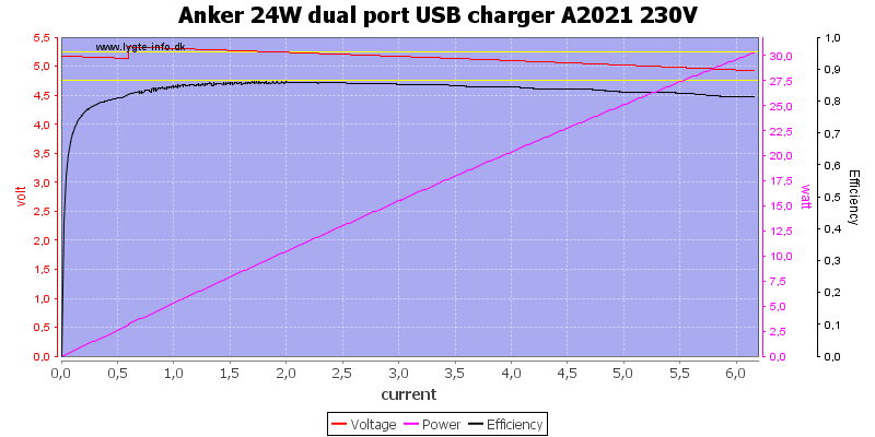
And slightly more at 230VAC
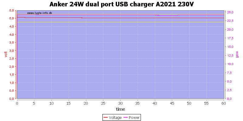
No problems running one hour at 4.8A.
The temperature photos below are taken between 30 minutes and 60 minutes into the one hour test.
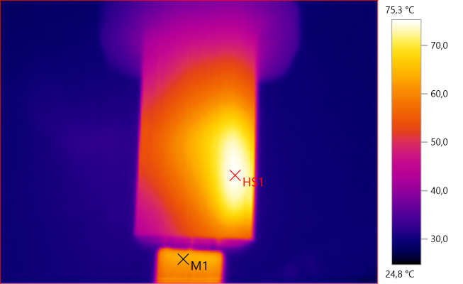
M1: 63,5°C, HS1: 75,3°C
HS1 is the rectifier.
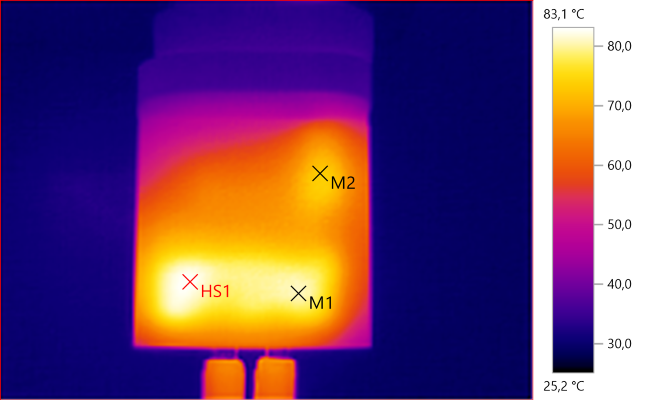
M1: 80,6°C, M2: 73,3°C, HS1: 83,1°C
HS1 is the rectifier.
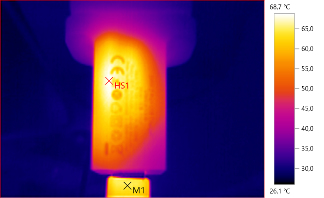
M1: 64,8°C, HS1: 68,7°C
HS1 is the mains switcher.
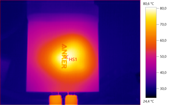
HS1: 80,6°C
HS1 is the transformer.
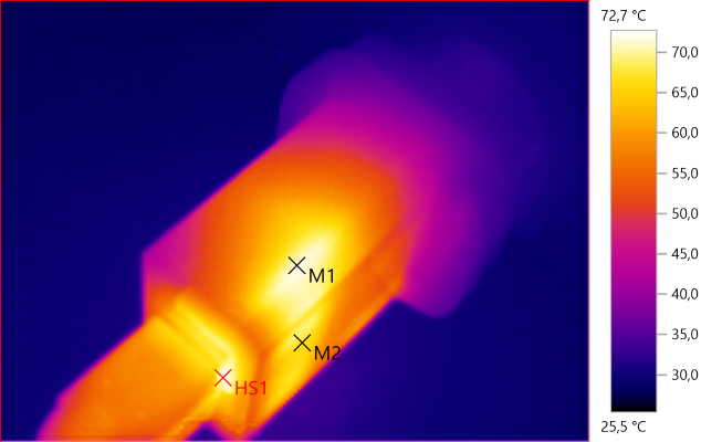
M1: 71,2°C, M2: 66,9°C, HS1: 72,7°C
HS1 and M1 is the rectifier.
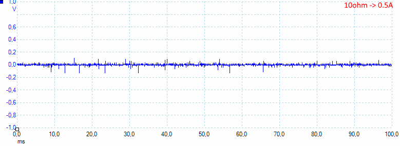
At 0.5A the noise is 8mV rms and 292mVpp.
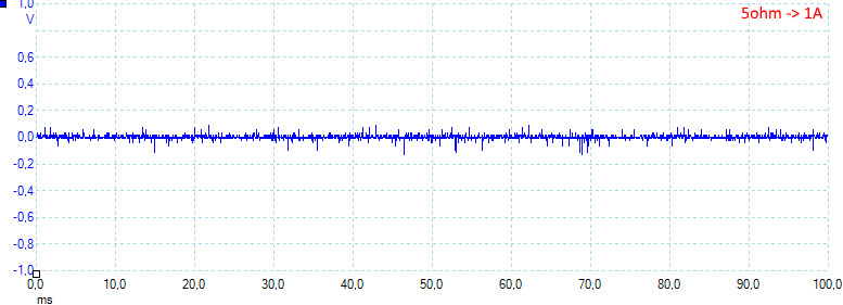
At 1A the noise is 11mV rms and 271mVpp.
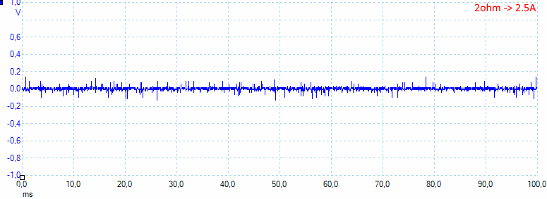
At 2.5A the noise is 14mV rms and 330mVpp.
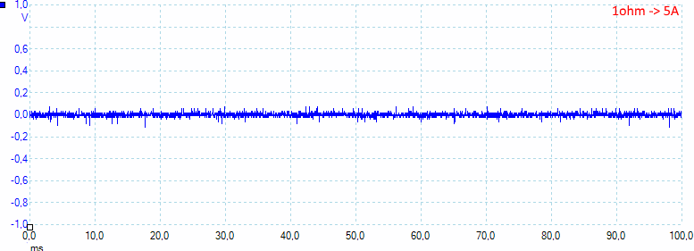
At 5A the noise is 13mV rms and 209mVpp, this is low noise.
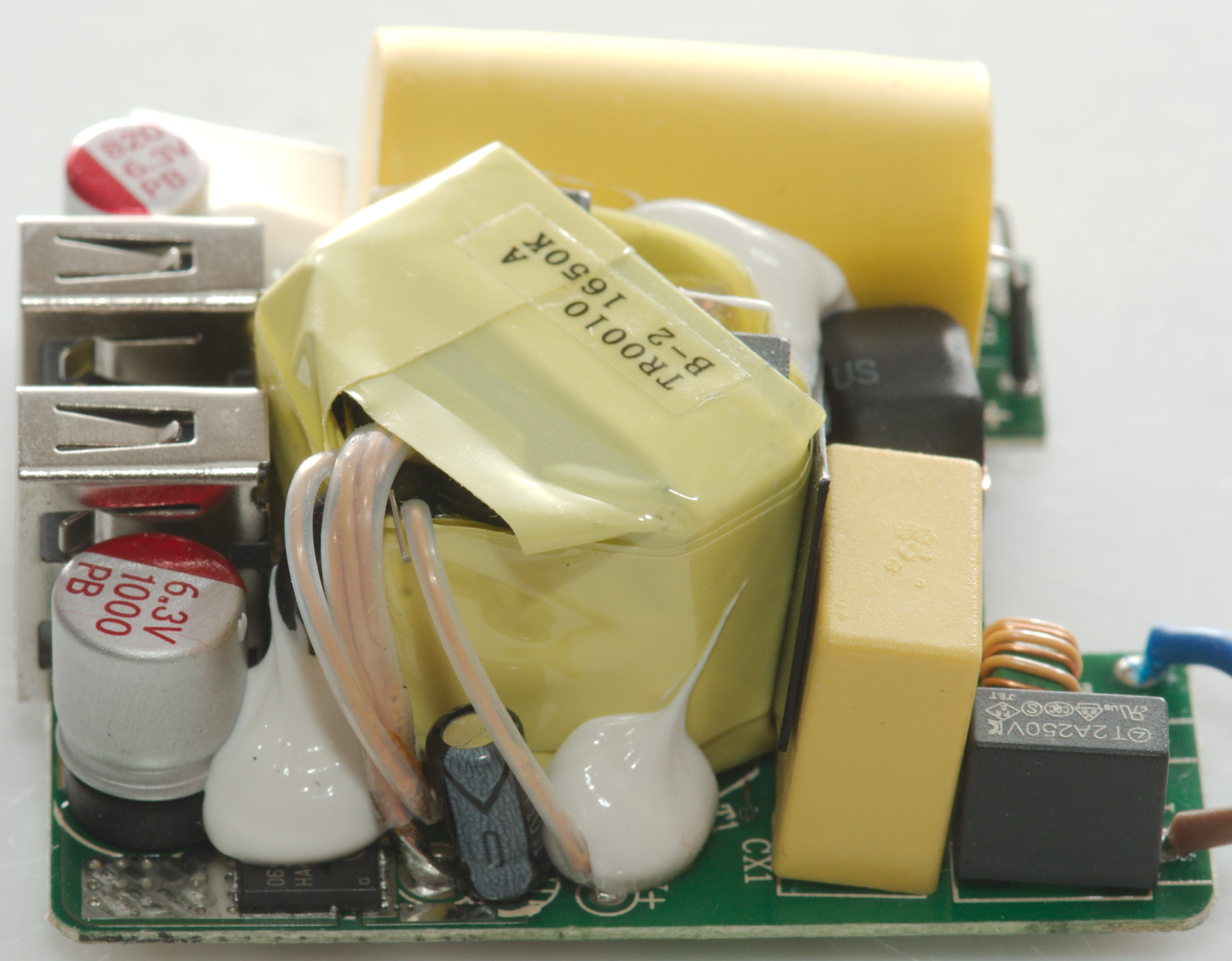
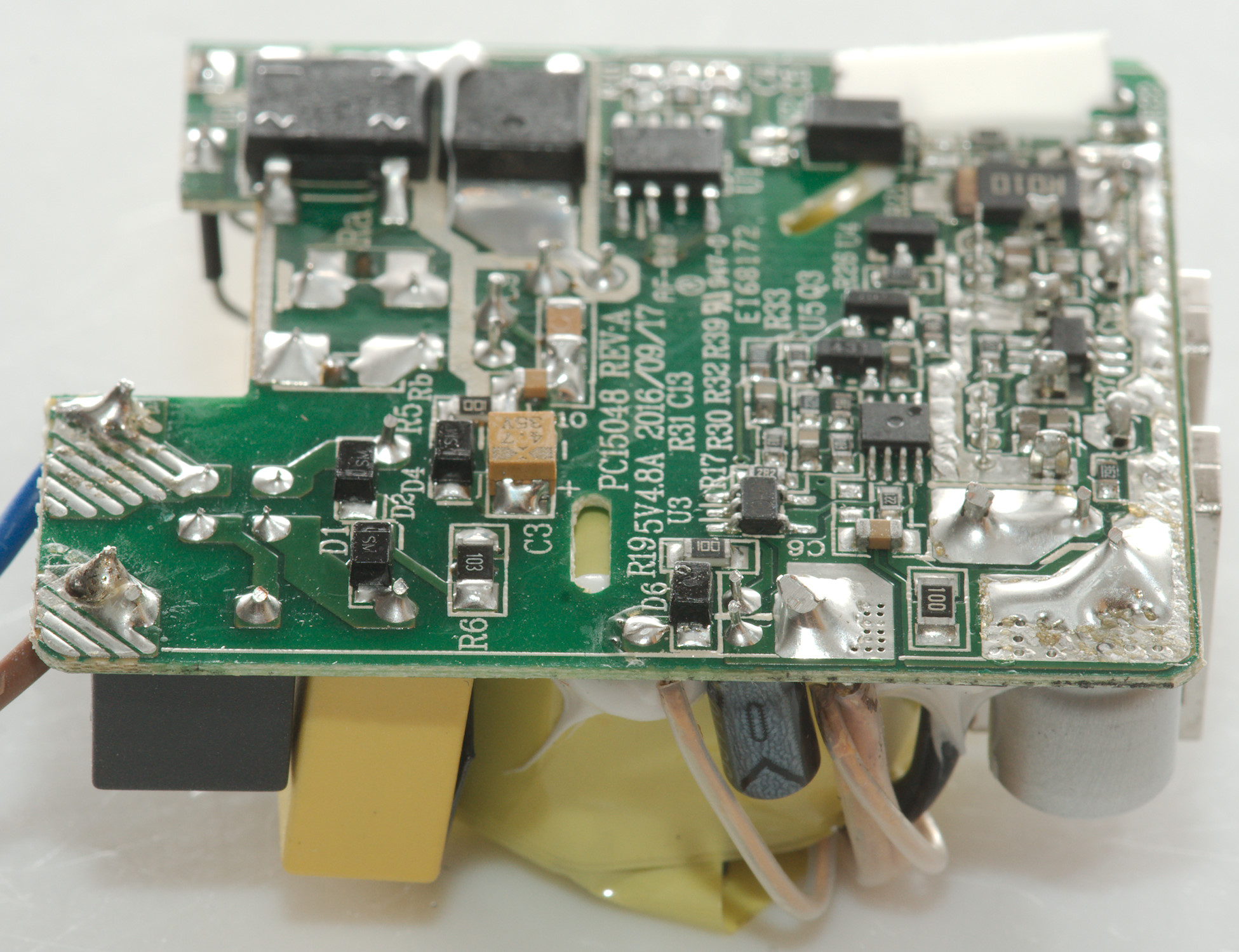
Tear down

Some pressure with my vice and I could break it open with a screwdriver.
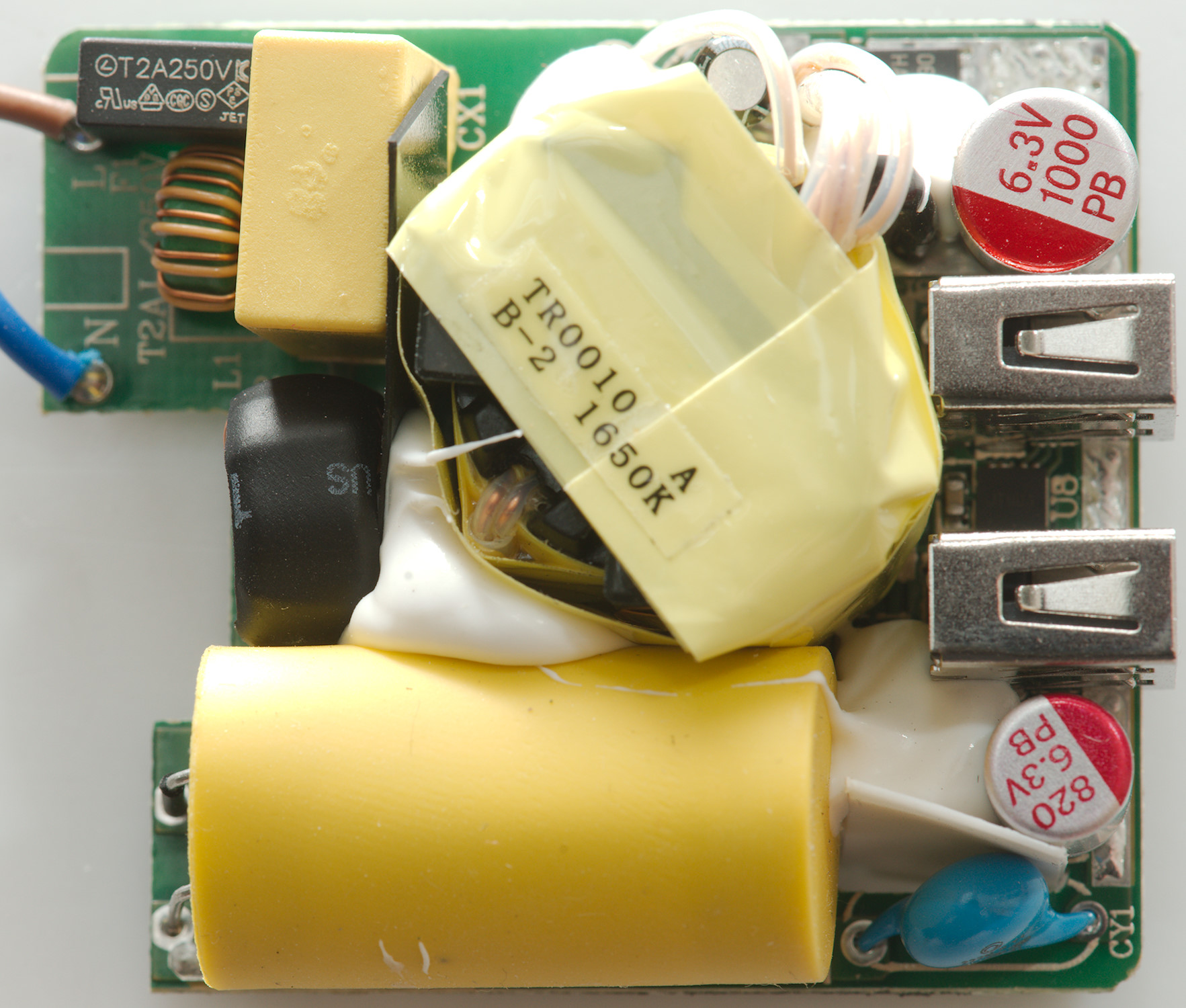
This is a very compact build with parts partially hidden. At the mains input is a 2A fuse and two common mode coil (L1 & L2) (L2 is in plain sight, but not obvious). Where the wires from the transformer is connected to the circuit board is a rectifier transistor (It is synchronous rectification). The chip (U8) between the two usb connectors is probably handling the individual current limits.
There is a blue safety capacitor (CY1).
Due to the compact size, there is a bit extra isolation paper/plastic between some of the parts and the big capacitors has a yellow rubber booth.
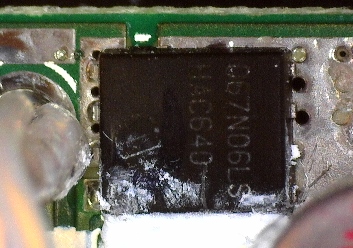
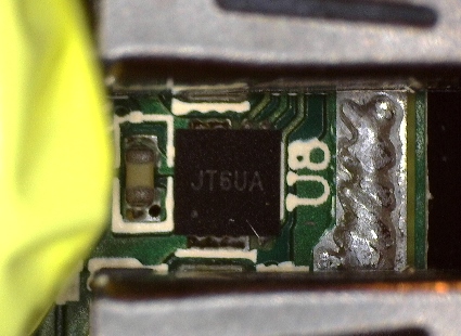
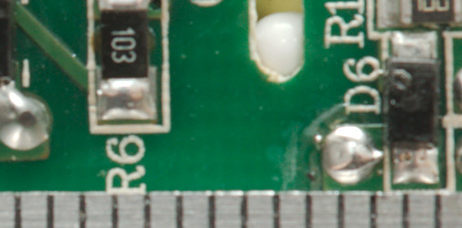
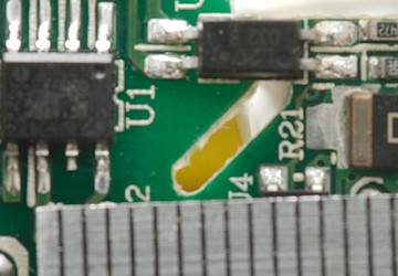
A closeup of the rectifier transistor and the current limiter chip.
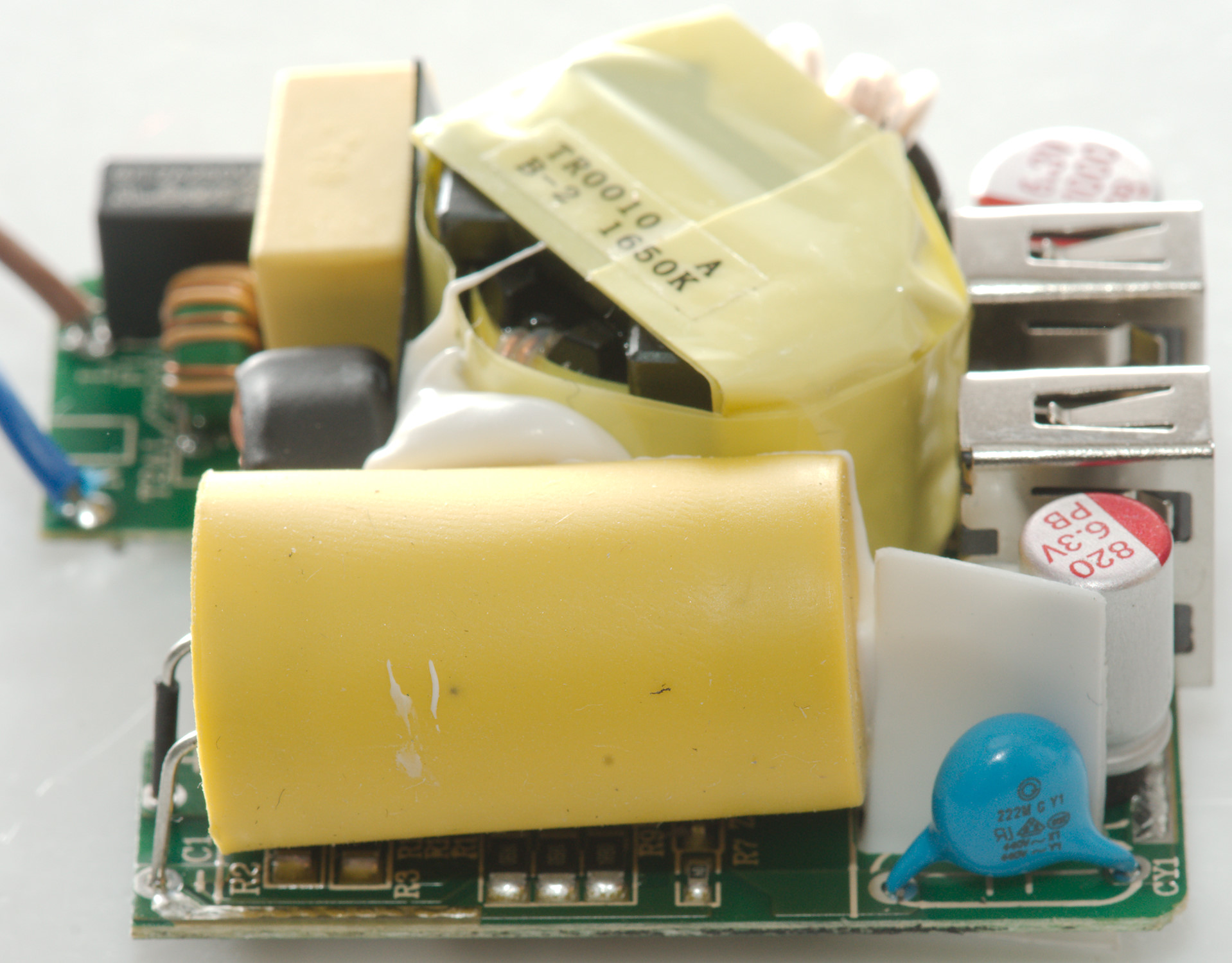
The mains capacitor with it rubber booth and the safety capacitor with some extra isolation behind it.
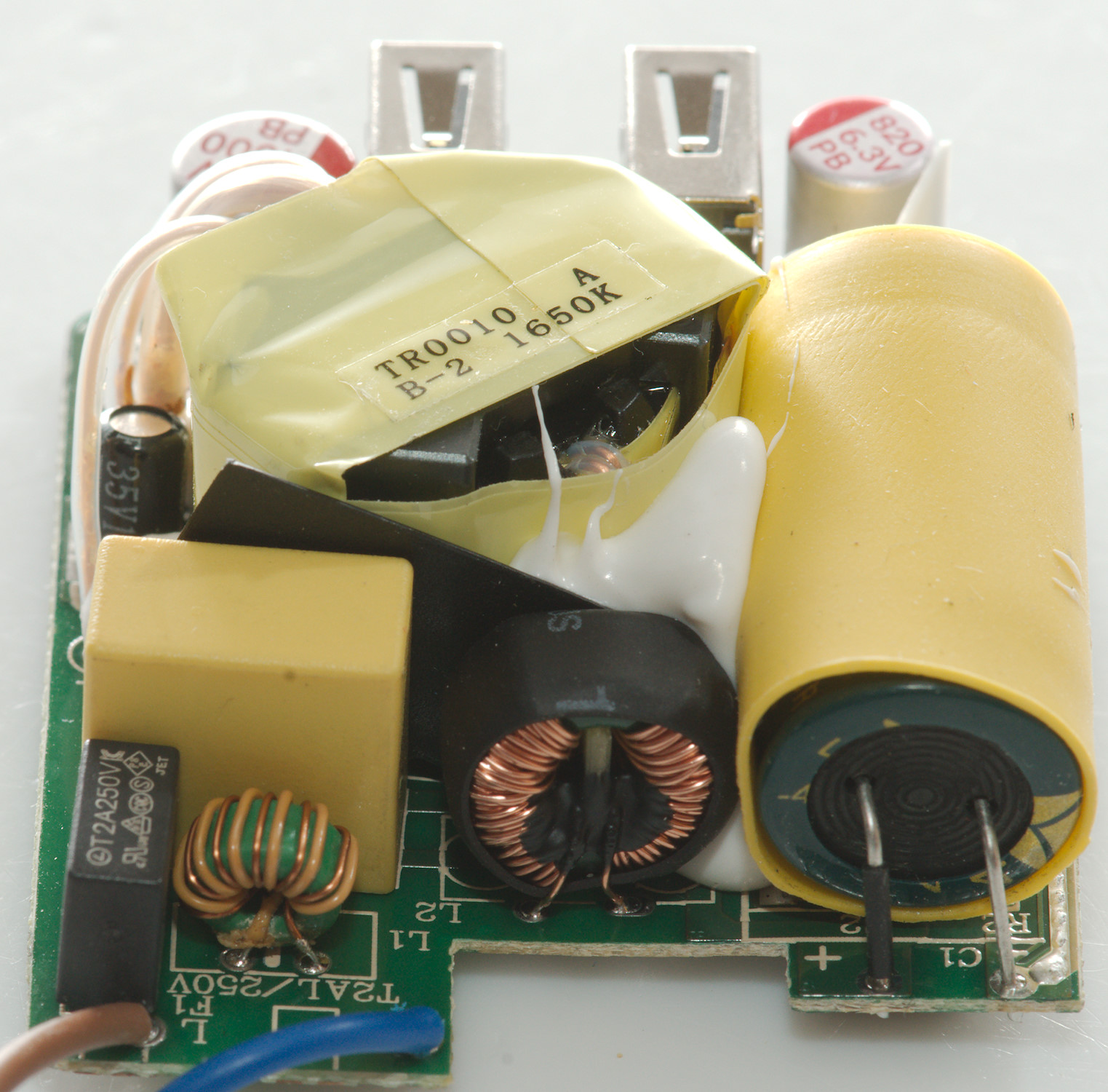
From this side the two common mode coils can easily be reconized.
Here the rectifier transistor is partial hidden below the white stuff.
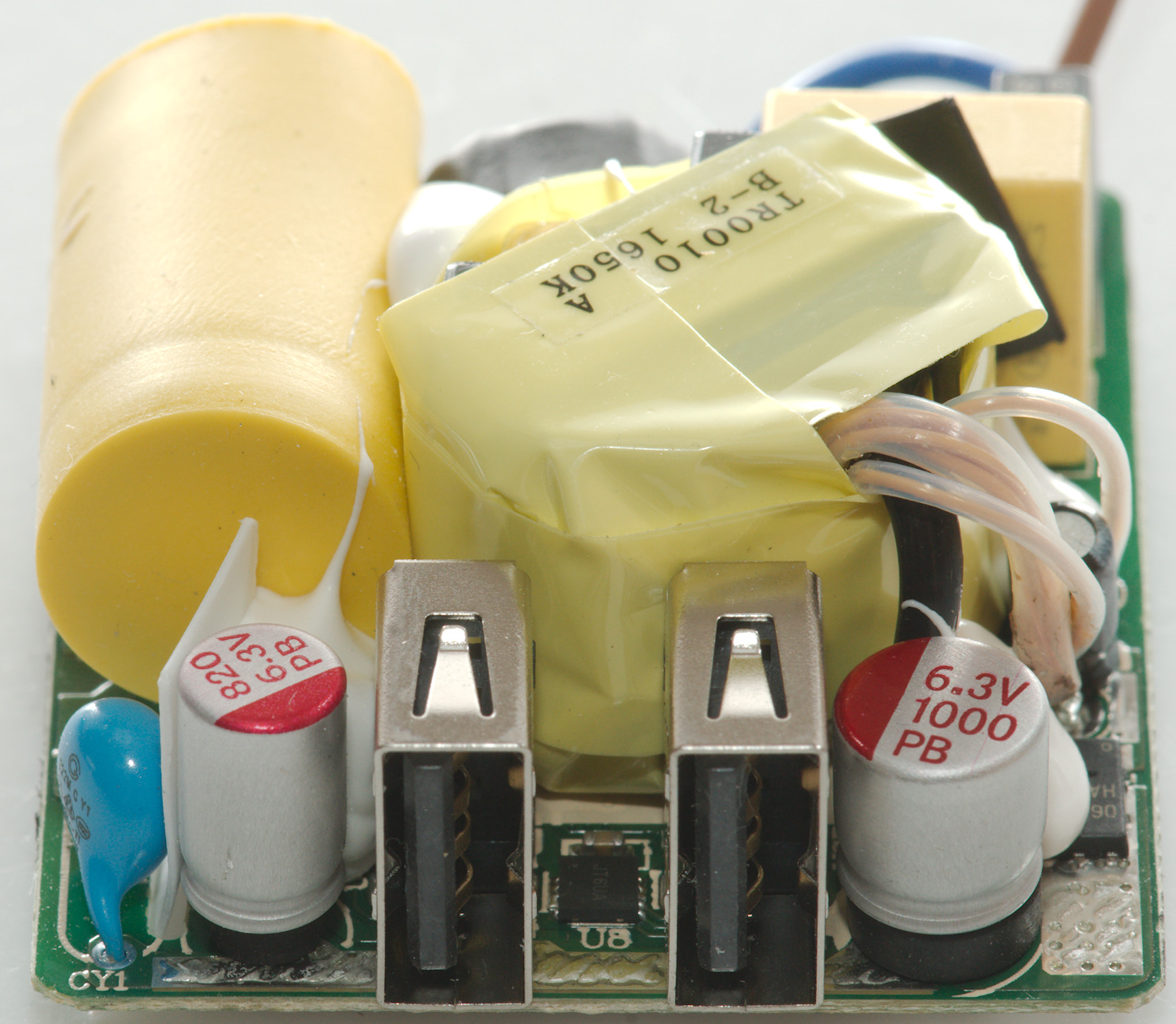
The gray rubber is there to transfer heat to the case.
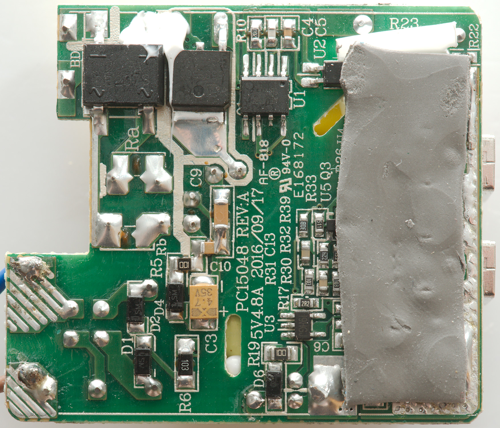
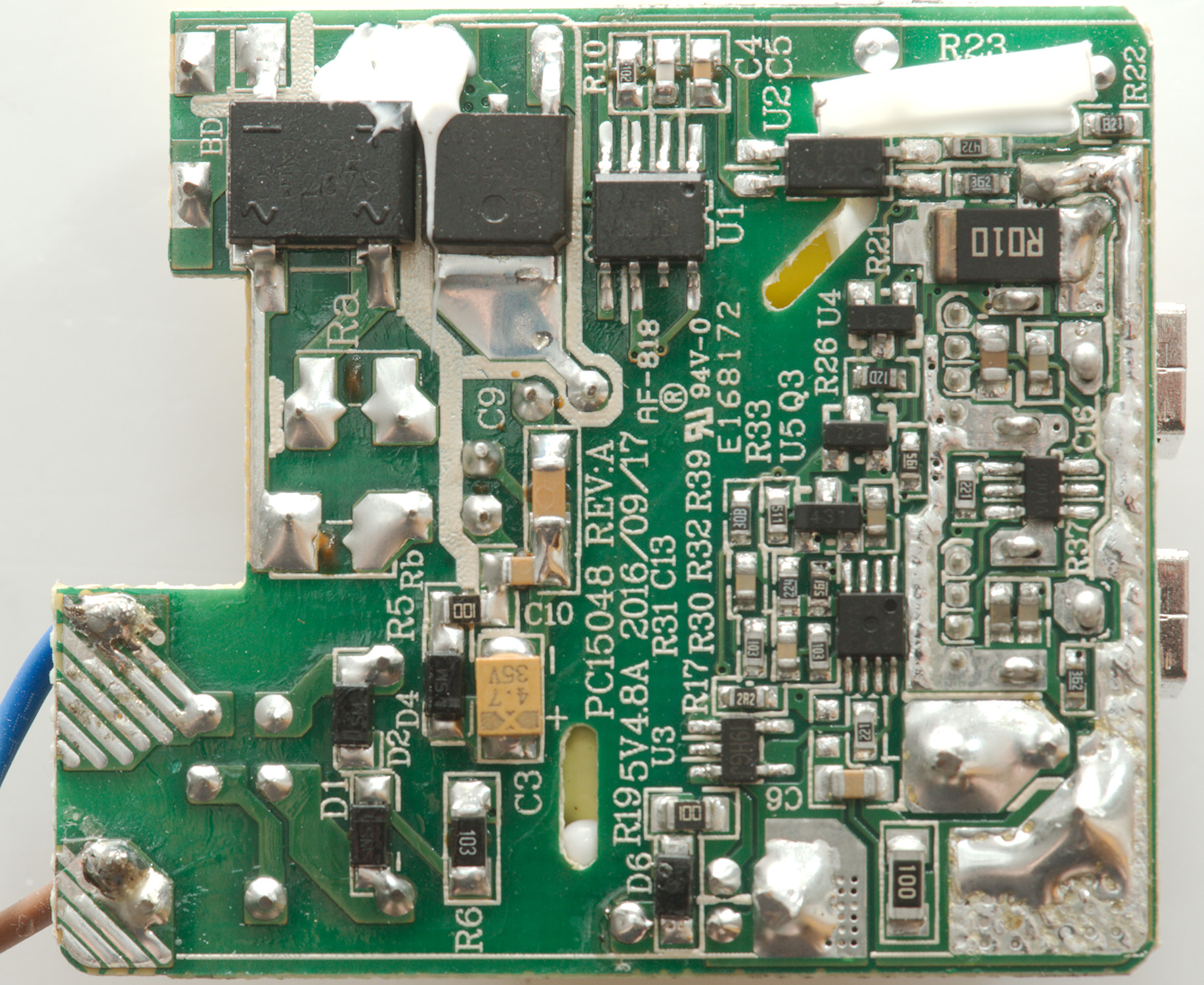
At the input is a bridge rectifier with the mains switcher transistor just beside it and then the mains switcher controller (U1: NE1118C) and on the same line is the opto coupler (U2).
On the low volt side is the reference (U4:431). The 6 pin chip between the usb connectors is the dual auto coding chip (CW3004). The chip U3 is probably the controller for the synchronous rectification.
But that means there is a two chip that I cannot figure out what do (One is a 431, the other is the 8 pin without a number). They may be a because the synchronous rectification need more than one chip or it may be a OpAmp used together with the power resistor (R21:10mOhm) as a global current limit.
Safety distance looks accetable.
Testing with 2830 volt and 4242 volt between mains and low volt side, did not show any safety problems.
Conclusion
The charger can deliver 2x2.4A with individual port protection, has auto coding, low noise, good safety
This is a very good usb charger.
Notes
The charger was supplied by a reader for review.
Index of all tested USB power supplies/chargers
Read more about how I test USB power supplies/charger
How does a usb charger work?