A few weeks ago I noticed that the NANJG-18 was listed as not suitable for use with a Li-Ion battery in TorchBoy’s driver data base. Since I have used this driver in some of my lights and it seemed to work without problems, I asked him about it and he replied that it was a pure boost driver and would go to direct drive if the input voltage was above the configured output voltage. I did some googling and found out that the circuit is based around the Seiko S-8352D constant voltage regulator. In fact, it seems to be the reference design from page 26 of the datasheet.
To make things easier to see, I created this little picture mapping the parts on the driver to the parts in the schema.
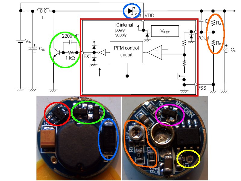
There are only two notable differences. First, the bipolar transistor (green) driving the inductor has been replaced by two FETs wired in parallel. Second, the voltage divider RA/RB (orange) has been made adjustable in order to make the output voltage adjustable. The values for RA/RB range from 30kΩ/20kΩ to 40kΩ/10kΩ. The regulator chip tries to keep a fixed voltage at its VOUT-pin. By using the voltage divider, the actual output voltage is a multiple of the voltage seen by the chip. If I got my math right, the output voltage should be adjustable from 2.5 to 5 times the regulator’s target voltage. Unfortunately, I couldn’t figure out the actual target voltage with my cheap DMM, it seems to lie somewhere between 1V and 1,3V. Given this design, there is no way to reduce the input voltage and the circuit will indeed go into direct drive when used with a standard LED and Li-Ion battery.
So, does this circuit work with Li-Ion? Yes and no. It’s possible to use this circuit with a high Vf LED like an XR-E. A single cell’s voltage will almost immediately drop to ~4V under serious load and the Schottky diode in the current’s path will drop another 0.2V, so you end up with 3.8V across the LED. That’s very close to the XR-E’s Vf at 1A, so there shouldn’t be a problem. Things are different with an XP-G, which has a Vf of ~3.5V at 1.5A and will be seriously overdriven at 3.8V.
If you’re using this driver with an XR-E, you have to be extra careful when adjusting the output voltage, as this circuit will happily suck a lot of current from the battery in order to reach its target voltage. I once forgot to dial the pot down and ended up with a burnt out switch in a matter of seconds. OTOH, if you manage to adjust it to 3.5V - 3.7V, your light will will keep a constant brightness until the battery’s protective circuit triggers.
Modes are controlled by an MCU, which in turn controls an FET (pink) sitting between the LED’s negative lead and electric ground. Modes can be disabled by soldering the LED’s negative lead directly to ground.
I used to be puzzled as to why there is a gap in the MCU’s power trace (yellow) that needs to be bridged to get this driver working. After figuring out how this circuit works, it actually makes sense. The MCU is powered in parallel to the LED and, according to some reports, the output voltage can be adjusted up to 7V, which would fry the MCU.
Okay, that’s it so far. I’m no EE, so anything written above should be taken with a grain of salt. Comments are always welcome.
Tido
Thanks for the driver tips Tido. Is it that some driver pots on this model wont allow you to adjust it to your spec of 3.5V - 3.7V? Ive also visited torchboys driver thread but still struggle with the accuracy of the information. Items change specs without warning, and consistency from unit to unit often varies considerably. At least DX provides forums to discuss these changes and variations.
If you’re calibrating for Li-Ion only, it’s a piece of cake.
But I usually put this driver in lights or drop-ins I want to use with different battery configurations and finding the sweet spot where it’s bright enough on a single NiMH without frying the LED on a Li-Ion can be a bit taxing.
Hey Tido, do you know what pulse period is generally used for PFM density out control circuits (not necessarity the power side one here)? Unless they're really short, it seems like a bad control scheme for low density low modes because it would space the pulses too far apart..
Agenthex, I’m not quite sure I understand your question. If you refer to the step-up circuitry, switching frequency is usually in the range of 100kHz and up, to keep the energy storing components small.
If you’re talking about controlling the LED’s light output, I’m not aware of any driver using PFM to do this. It’s usually done with PWM and duty cycles of at least a few hundred Hz, the higher the better. The ATTinys used by a lot of drivers can easily achieve PWM frequencies of 1kHz.
I was talking about the "mode" drivers. Thanks for the info. :)
Thanks for you work and insight with this driver.
So are you saying that one should bridge that gap or not?
I like this driver for 2AA applications. If I'm building a light for someone who uses std batteries I can wind it down, if I'm building for me using eneloops I can wind it up.
You'll need to bridge the gap if you want to have a multi mode light. For a single mode one, you can just connect the LED's cathode to ground.
The only reason not to gap it would be, if you cranked the circuit up enough to drive two LEDs in series and the combined voltage drop would exceed the MCU's maximum voltage specs. In this case you could gap it with a resistor instead, to lower the voltage enough to stay within the MCU's operating range.