Bicycle simple PWM XPG2 with tp4056 charger

Hello!
I want to create simple driver for XPG2 led for bicycle running from one 18650 battery.

The first problem: i am not familiar with electronic schematics, i am a microcontroller’s programmer, so i decided to ask help here.

I hope that everything has already been invented before me, so may be anyone knows a good and simple schematic of PWM’s controlled led and microcontroller (ATMEL for example)?

I have searched the Internet, and discovered that all of such schematics consist of mosfet and microcontroller, which controls led by PWM to this mosfet.

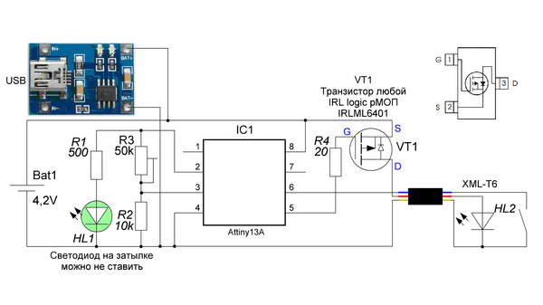
I want to use ATTINY85 as MCU, cause i know it well.

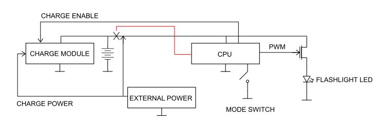
And the second problem - it is the charger. I knew the very simple schematic based on tp4056 chip. But i want to control internal charger and battery by MCU.

I expain why:

1. if led is on and no external power is attached - MCU controls the discharge of internal battery and generate PWM to the XPG2 and controls LED temperature - it is normal mode

2. if led is on and external power is attached by external battery near 3.7v - internal charger and battery must be switched off, now MCU controls external power discharge (like it does in 1) - it is external battery mode

3. if led is on and external power is attached and it is near 5v - internal charger and battery must be switched off, microcontroller stops to control the discharge and simply control only led - external power mode

4. if led is off and external power is attached and it is near 5v - charging of internal battery is started - it is charge mode

How can i achieve it? And i am very limited of PCB size (because of case of the flashlight).

What is the better mosfet for XPG2? SI2303 is good enought for it?

P.S. thank you for any information
P.P.S. sorry for my bad english

The TP4056 has a chip enable (CE) input on pin 8. Logic high is on (charging), low is off (disabled). Datasheet:

Took a quick look at the SI2303 datasheet:

and it doesn’t look very good. It’s low power and needs more gate voltage than a single 18650-based circuit can supply.

Any reason you’re considering a P-channel MOSFET? N-channel is usually better / cheaper for a given specification.

We have plenty of driver circuitry floating around here for you to peruse. You can just use the search box top-left to search the word “driver” and find many threads. We’ve been using ATTiny85 for our most recent designs, and firmware written by our members. But you can find a driver design that you like and program it yourself, if you want. Most designs are open source, which means you can buy the parts and build your own, or even change the design to suit your taste, if so inclined. However, some members are building and selling complete drivers, so you don’t have to build your own if you don’t wish to.

Look for driver designs by these members:

Lexel
Texas_Ace
DEL (although he’s been absent for some time)
HarleyQuin
…and others

And you can get started with firmware from:

ToyKeeper
Tom E
…and others

OH yeah, if you wish to include the charger as part of the circuitry on the driver, you can contact Lexel about his lantern driver. It uses a different chip than the TP4056, but is still a decently priced and slightly better chip.

@Ionic, you should use a TP5100.

Uses a buck circuit rather than linear, which means higher voltages are supported, along with being more efficient.

Thank you for answers - very useful.

About p-mosfet - i saw it on native pcb of flashlight, which i use as a case. Okay, if n-mosfet is better, which one i can use? Will be great if it has a small size.

About enable/disable pin - looks good, but i need to switch off battery too - that is a problem.

TP5100 - i look through its datasheet - can’t use it because it requires more space on PCB than i have even without driver :slight_smile:

And about drivers - most of them use AMC and need more space on PCB tha i can use.
For example: 1.5A (max XPG2) / 350mA (AMC) = 4, so i need four AMC chips on board - they need more space than i have on it.

I want something like this (right part of schematic):

But relative to this schematic i don’t know - it is good enough for XPG2 (if i remember well its max current is 1.5A).
How effective such schematic? And why they used p-mosfet instead of n-mosfet?
And main question about such schematic - when i switch on mosfet, what is the current will be on led? I need it to understand, which frequency i should use in PWM.

That IRLML6401 isn’t bad for such a small device, but I’m not convinced that it’ll handle full power on the direct-drive LED I see in your schematic, even with PWM restricting it. In your design, the LED current will basically be “as much as it can get” whenever it’s on.

IRLML6401 datasheet:

The IRLML6401 comes in a SOT-23 package, which is about as small as you can go for sensible hand soldering. Higher power MOSFETs will be bigger. Unfortunately, I’m not familiar enough with small high power MOSFETs to recommend one.

P-channel versus N-channel is normally a matter of what suits your design. If you can make either work equally well, N-channel MOSFETs usually have better device properties for less money.

I see you still have pin 7 available on your ATtiny13A. Can you use pin 7 to control another MOSFET that connects & disconnects the battery?

As far as LED current goes, you can’t rely on a given current when direct-driving an LED like this. You either make sure all components can withstand whatever the maximum current is likely to be (check the LED datasheet) or you control the current in some way.

Current control can be anything from a plain resistor (simple, but doesn’t compensate for falling battery voltage) through using AMC7135s (simple, but needs more space for higher currents) right up to putting a current sense resistor in series with the LED and dynamically adjusting the MOSFET gate voltage to get the current you want (much more complicated).

Thank you for the answer.

I can use all pins of ATTINY (include RESET), so i have enough pins to control something else.
My idea is something like this:

But i don’t know how to create normally closed relay by mosfet or something else (so it opens when no control signal, and closes with control signal) for place in schematic, which i have marked by “X” with red wire.

And one question more - okay, by you i know that this schematic will provide current “as much as it can get”, so may be it is possible to limit it by 1.5A? Independs from volatage?
Something like linear controller, something like AMC7135, but not for 350mA, but for 1.5A? I don’t care if current will be less than 1.5A - because it doesn’t harm the LED.
In this i can use PWM on such controller - and it will compact and fits all my needs.

Mike C has used 1A rated current regulators for his drivers HERE. He isn’t really talking much about his driver design. But, if you PM him, he would probably tell you what those regulators are and where to source them, and maybe how they connect in the circuit. That should save you a lot of space compared to AMC7135 regulators.

A quick search online tells me there is a type of FET that is “normally closed” and is called Depletion Mode whereas the most commonly used FETs are typically “normally open” and are called Enhanced Mode FET. I don’t know how that works, other than the obvious implication that it will “conduct” when it is at zero volts and then when voltage is applied it stops “conducting”.

Oh yeah, why does your circuit need to be small? Do you have a specific host to use, that is space limited?

Thank you for mosfet info - will try to find something.
I have looked to MIKE C schematic - he has used CN5710 linear driver, and according its specification its max current is 1A. If i remember well XPG2 under 1A current has 400lm.

Yes, it is host like this:

It has internal PCB about 10x30mm with available space only on 1 size about 10x20mm.

Well, 10mm x 20mm is not that small, really. We do have 10mm diameter driver designs already. Also, DQG 10180 size flashlight chargers fit in a 10mm circle and use a micro USB port. So, with a full 10mm x 20mm rectangle, you should have plenty of room to put everything. That is over 25% larger than two 10mm circles! But why are you limited to that much space on the PCB? If you had your own designed PCB, is there any way you could make more of that space useful? If you could add two of those regulators, you could have up to 2A to the emitter.

I have got a photo of PCB:

Back side has only micro-usb socket.