Hello Guys,
First I have to say Im new to the forum and to modding, but Ive spend some weeks reading the posts and have learned already a lot from you! I’m very grateful for that.
This will be my first post so please take easy on the newbie here!
My objective is to Mod this flashlight, which is a chinese clone from a real firearms flashlight from Streamlight (TLR-HL); **flashlight wont be used for military / security purposes
Im aware I cant trust the clone for that).
So, to get started I wanted to know what is in there, this Is all I want to cover in this first post…the mods intentions will come in the next in the same topic.
For that I disassembled the light and made some tests ( please criticise if you dont agree with them).
Flashlight characteristics:
Batteries 2x 16340 in series
Current Led: XM-L2 ( alleged by the seller)
Driver: I didn’t know which driver it had so I tried to measure the amp draw and voltage output by I method I saw in another forum ( please comment what you think).
Considering it is really XM-L2 I believe the driver should be “step down driver” (3V led vs 2x batteries in series), So I googled the name of the bigger electronic in there called 4R7 and it matched with a inductor…so until now everything makes sense for me.
So after that I kind figure out what I wanted with this, the current output ( around 2.6 amps) but I got surprised because the
voltage with no resistance was the sum of the two batteries ( around 8V) . Shoudn’t the driver reduce the voltage even without the LED resistance?
As you can see in the pictures the driver has a different format, is not a circle, it has room for the two screws for the pcb and it also can only by installed by the front, so I believe I will have to keep the driver and try to improve it If I want more current output, what you guys think? Thanks!
I can't make out most of the the driver components, but the few I can see indicate that you are correct about it being a buck driver. A buck driver will step the voltage down to what ever the load draws (with in the driver's limits). Basically, the excess voltage builds up in the inductor (the component marked 4R7"). Once a set voltage is reached, the power from the cells is cut and the voltage built up in the inductor is consumed by the load (LED's).
The maximum amount of current that that is allowed should be controlled by a voltage sense resistor. Appears to be mostly buried under flux next to the black wire. Maybe use some alcohol to clean up the driver and take a better picture. A picture of the other side of the driver would be handy to.
Hey! Thanks for the answer;
Here are some hi-quality pictures with a better camera; I tried to disassembly it to take some from the back of the driver but it seems to be glued and I was afraid to force it and break;
There is also a picture from the rear part. The two bigger solder points lead directly tho the connections on the back.
Hmm, can you read the markings on the large resister that appears to be connected to the black wire? I get the impression that it is all zeros. If that is the case, it appears that your driver is already set to max current.
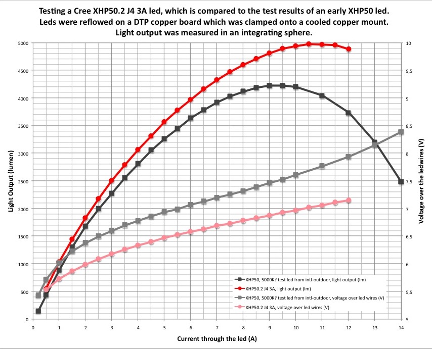
If that is the case, don't despair. The XHP50.2 emitter has the same footprint as the XML. It runs at about twice the voltage (6 volt emitter) and also should be more efficient than your existing emitter. I'm not up on what is the most efficient XHP50.2. So maybe another member can provide some recommendations in that regard. Here is a chart of an XHP50.2 that was tested some time ago by djozz. It shows the emitter producing around 2200 lumens at 2.6 amps. I don't recall is that is bare emitter output or if it factors in typical losses that due to reflector and lens inefficiencies. Chances are, there are even more efficient XHP50.2 emitters by now.
Your cells might not be up to producing the current needed to push all 2.6 amps to the XHP50.2. This would be due to voltage sag caused by doubling the wattage they will be producing. Another limiting factor might be your light's ability to shed the additional heat. Probably wouldn't be a problem as I imagine you wouldn't run the light for long lengths of time. Additionally, the light will be mounted to your weapon and not in direct contact with your skin.
If you upgrade to an XHP50.2, you would want to make sure it's on a direct thermal path copper base that is in very good contact with the body of your flashlight.
Just throwing out ideas. My flashlight knowledge is a bit dated. So better information may be forthcoming from other members. In the meantime, please tell us what the resister marking is.
Hey there!
Running a xhp50.2 would definately be amazing!
So, at first I also thought it as 000 but no, see below please. ( click to zoom )
Would the buck driver deliver 6 volts instead of 3 volts for the XHP50.2 without me changing anything?
About the overheat…that should be no problem since I only use short bursts…like 3 seconds on at 100% than 5 seconds off than on again…repeat like 15 times and that`s it…than I give it a long break before repeating
No problem Fabio. I appreciate how you have provided good information, pictures and current/voltage measurements before asking questions.
Yes, your driver should have no problem driving a 6 volt emitter as long as the power source can keep up. It should actually be easier on the driver as there will be less voltage differential between the source and the load. If the cells can't keep up, the driver will just not deliver max current (2.6 amps with the .1 ohm voltage sense resister currently in place). If you want to test, you can connect another emitter in series with your current XML.
So regarding increasing the driver's current output. You can do that by decreasing resistance of that voltage sense resister. I don't recommend you do that unless you have good soldering skills. That driver will try to suck heat away from the soldering iron. You can damage the driver if you don't know what you're doing. There is also the risk that some component on the driver will not be able to handle the additional current and fail. That is not likely though. I think I have been able to dead short the voltage sense resister on every buck I have played with success. None of them failed, but some were not happy. What does happen though on many drivers though is that the current increases for all modes. Sometime so much, that there is very little difference between the light output in the low modes and the highest mode.
If you really want to play with increasing the output of that driver, I would suggest soldering a wire to the end of the resistor that doesn't have the black wire connected to it. Then, you can try out different resistance levels by soldering resistors between the ends of the new wire and the black wire. That way you are not repeated subjecting your driver to the high heat of a soldering iron. There is no need to remove the existing resistor as you are wanting to lower resistance.
Hope this is helpful information. Take care Fabio.
There are XHP50.2 3V emitters.
Nice Youtube video with Matt on reflowing a led.
So keeping the driver as is, your output would be in the 1400 lumens versus the present 800’ish. Same 9 watts.
I don’t think you would even have to piggyback another resistor to R100 (to lower the sense current). The cells would draw some 1.4 amps each (quite reasonable for 18340 LiIon).
But adding another R100 in parallel, could draw some 2.8 amps (if the cells can sustain) and beef up the output to the aforementioned 2200 lumens.
This is theoretical, but by experimenting you would get some insights.
ImA4Wheelr thanks for the great help!! I always like to provide lots of information to try to explain myself the best I can!
So, I believe the power source will be able to keep up… I’ve got a pair of Keeppower 16340 shipped on the way. I have also some unprotected 18350 on the way that might fit with some sanding on the flashlight shell.
I made the test with leds in series and it lit both leds . A xm-l2 and a xpl-hi mounted on a convoy S2 . Now im not very sure if I should have dismantled the xpl from the 7135*8 driver but I don’t have my soldering iron with me now for that. Currently Im still using shitty unbranded 16340 batteries.
(Xml on Pcb in series with convoy xpl-hi head )
The current dropped to 1.6 amps ( see picture) but I’m drawing 10Watts against 8.5W from the first tests with 3V led only.
Sidney Stratton , thanks for the answer aswell;
Unfortunately I cant find the XHP50.2 3V from sellers that sell to Brazil at reasonably shipping costs;
Now what I haven’t understood:
Changing only the battery for hi-drain ones would provide it more current for the 6V led without further mods? But never the 2.8amps I got initially with 3V, right?
Changing only the battery for hi-drain ones AND soldering another R100 in parallel ( like in pic below) will theorically give me the 2.8 amps being limited to the cells, right? Thanks!!!
I believe Kaidomain ships to Brazil at good rate. They have both 3 and 6 volt XHP50.2 mounted on MCPCB (“star”).
Apon reflexion, I may have errored. Changing to a 6 Volt LED the buck circuit may be able to provide the 2.8 amps. If it can’t, the sense resistor may have to be reduced. The driver is tuned to the XML, now you want to tweek it to an XHP50.2.
As you tested 2 leds in series and they do work, a 6 Volt LED will also work. With leads soldered to the R100 you could test a few values to bring the current up.
Hey!
As far as I understood those leds with voltage variants tend to deliver the same light output per Power. So a 3V at 2.8 amps is equivalent to 6V at 1.4 amps, did I get it right?
because if so I prefer the 6V since they have the 3000K variant! By the way thanks for remembering me about Kaidomain…the options Ive found so far is just fastTech and aliexpress.
I started to look for resistors and I found out I must also specify its power… how do I figure
out the one I have to get the same? Thanks
That is correct. And that is what initially threw me off. However the buck converter adjusts the voltage to the load drawn. The limiting factor is the sense resistor.
I went down a rabbit hole by looking over some tests by TexasAce on this forum - search XHP50.2
Best get the highest power that can fit over the existing one - a bit larger can be soldered on.
Best get the highest power that can fit over the existing one – a bit larger can be soldered on.
There are two resistors, each delivering their share of power. Another R100 would draw 50% the power so no big deal. A lower value would draw more so higher power resistor. I pull these resistors from trashed PCBs, not much choice in power dissipation.
I agree with Sidney's comments above, except for me being better with these mods.
The formula to determine what minimum wattage resistor to get is volts times current. If you measure the voltage difference over your existing resistor (simply probes on both sides of the resister), you will know voltage. If you plan on driving at 2.8amps, you just multiply 2.8 times your voltage measurement. As Sidney said, divide the wattage by the number of parallel resistors (assuming all the resistors have the same resistance rating). A also agree with Sidney in going with the largest resistors you can fit. Nice to have a safety margin.
I would expect the driver to provide the same amount of current (2.8 amps) as long as an adequate power source is connected. I suspect that the decrease in current for your test above is due to one or more of the following:
Your driver may be designed for more voltage overhead than your power source can provide.
Voltage sag in the cells.
Thin leads that may be restricting the higher wattage now trying to flow through them.
A or some driver components not able to handle the additional wattage. Check to see if any of the components get uncomfortably hot within a short amount of time.
Hey guys!
So…i did some redneckish and pulled 2 wires from where the batteries should be and connected one 18650 and one 14500 battery in series outside the shell ( used what I had here)
and… now Im getting 2.1 amps at 6.5V around 13.5 Watts! So it proves one of the the bottlenecks was the batteries.
The other is for sure thin wires and bad connections… The tests were made in a hurry, without soldering anything, with lots of adhesive tape, myself holding everything together, etc.
I still gotta see if nothing is overheating like ImA4Wheelr suggested.
So I will see how much current I `ll get with the good 16340 yet to arrive here. If I get 2amps thats enough for me … So probably I dont need the extra resistor and problem is solved!
Going to buy some xhp50.2 from Kaidomain!
Now…Just for sake of curiosity:
In this last test setup If I had the extra resistor also would I still double the current to like 4 amps? Thanks!
Your cells couldn’t keep up at 4 amps. The driver is initially tuned to 2.6 amps and you could pull more with some tweaking.
I’d wait for the Led to be installed and with your Keeppower 16340s. You could then check the current draw and if any components are heating.
As I piggybacked some resistor that I salvaged from some PCBs, it is not always straightforward. I don’t like pushing the limit - then something breaks / burns out and I’d be left with a dead project.
Sounds like great news Fabio. Really looking forward to hearing back on how your mods go.
I think Sidney's advice about doing the emitter swap first and then going from there is good. Looks like you have a nice light that is holding up to the shock of your firearm. I'm sure you could install a new driver if the driver failed from such a mod. But, that seems like a lot of work to do correctly given the harsh conditions the driver would have to operate in. I guess I should not be giving advice that I tend to not follow myself.
Best wishes again. It's been fun seeing your progress so far.
P.S. Looking at your driver, it appears that the 6 pin component on the bottom of this picture is you buck converter. That is the most like component to fail for me when I experiment with buck drivers. Can you read the marking on the top of it?
Hey guys!! Thanks one more time for all the help!! I really got better in this thanks to you!
Ja Im not changing the resistor, I’ll run the xhp50 as it is…there’s also barely no room for heatsink to go full power…
In fact I’ve got another indentical flashlight coming…for that Im willing to drop xp-e2 red … probably will have to add a resistor in series to reduce the current a bit.
Lets see how they run and as my taste for mods increase and and Ill probably get a third one to change driver etc and try to squeeze max output…the ideas are already poping out in my head;;
might machine a slight longer front end for more cooling aswell.
This flashlight host is really perfect for my application…and also very cheap.
So, ImA4Wheelr, after some trial I got the pictures from that component. I Think it says LBAR.
please check pics below
Sounds like some exciting ideas. That 2S battery set up with a buck driver sure provides a lot of mod options. A red firearm light sounds like it would be handy for night hunting. Is that what you would use it for?
Unfortunately, I'm not familiar with that 6 pin component. I don't even know if its a buck converter. I was hoping it was going to be one I was familiar with so I could point you to a good source for replacements.
Please keep us posted on how your mods go. Really hoping they go well for you Fabio.
Hey!
Nope, the red one is for my Airsoft pistol…I use to use a flashlight and turn it on while shooting because it helps alot to see the white balls, the ammunition or pellets,so I can track my shots and correct the aim
faster than looking at the sights, and also it’good to catch them on camera with a GoPro I play with!
I think the red colour will give alot more contrast to the white balls,than the 6500k led…so I want to give it a try.
Thanks again for the help!! I will post the result as soon my shipment from kaidomain arrives! See you
Hey guys! how are you doing
My light is still running strong and well , much better than I first wxpected !! and I thank you all for that!
The reason Im here is because now I have a second identical light, which I want to make a red thrower…
I first gave it a try with the Xp-E2 led but I found it too weak… so I found the Osram Q7WP, which I found no topic covering it
but looked promising, so I bought two of them.
I created another topic for that because Im having some trouble installing it, I hope you could take a look ! thanks