Can someone tell this complete newb what the tail cap measurements mean? I'll read a review and there is always a bunch of people that post about the readings. What do the measurements mean? Is it better to have high or low readings?
Everybody is reading the input current and try to approximated the lumen output. However an imprecise method of doing that, because of several factors.
Theoretically the higher the better, but values are not incrementally perfect. Like 3A current compared to 2.8A current is not going to offer a 7% percent increase in theoretical lumen but only 3.5%. Or from 2000mA to 2800mA there is a 40% difference and the increased lumen output is 25%.
Temperature (or heat-sinking capabilities of the whole flashlight) and driver efficiency have a true impact on output, not to mention batteries on direct driven flashlights.
It measures the amount of current the LED and driver are drawing from the battery. You bypass the switch and put your DMM there to complete the circuit and measure the current. It's a rough estimate of output of the light. But it doesn't tell you how much power is actually reaching the LED because the driver could be 90% efficient or 50% efficient and the tail measurement wouldn't tell you. Also, if you have a really, really bad switch, you are bypassing that when you take a tailcap reading, so some of these very high reading may not 100% accurate.
However, if the light is only drawing 0.5A and it should be drawing 1.5A, then you know why it doesn't look very bright. So it is useful.
tailcap readings could be used to estimate runtimes. in 50% of the cases you'd get a very accurate runtime estimate. and in the other 50% the estimate is totally off (200-300%).
it is sometimes interesting to know how much current is drawn from your cell, for example i find 2C pretty critical for a 1x AAA torch, and personally i wouldnt buy any 1x AAA or 1x AA torch which draws 2C or more from your single cell (Eneloop or LiIon) in High-mode.
poof, dude!!
The numbers are only co-relative to other numbers taken with the same DMM.
If I measure all of my lights and say....
X9, 2.8A
KD C8, 3.2A
XinTD C8, 2.6A
Keygos KE-5, 3.6A
Then you have some relative numbers to compare by.....but they do not compare INDIVIDUALLY to some other guy with another Digital MultiMeter. His meter might read higher or lower than mine.
Measuring the current to estimate runtimes is not something easy, useless you have a constant current draw. For the regular lights that are direct drive or or partially direct drive the estimation cannot be accurate as the voltage drops and the current draw decreases, and the battery model has much to do with what is being drawn.
Measuring current on a circuit that increase the current draw across the discharge is again inaccurate, eg..boost . Estimating current on medium and low modes by reading the current that is PWM controlled can be again again misleading as the current is not a pure form a of DC current but a chopped current.
If you know why you measure the current, well then it's useful. Different DMMs will measure differently...... but that's another discussion.
tailcap readings are always taken with absolutely fresh cells right off the charger (e.g. 1.54V for an Eneloop, instead of the usual 1.47V) so that you get the LOWEST amperage reading possible.
constant brightness regulated lights: amperage will increase slowly (at the beginning) when cell voltage decreases (1.54V, 1.53V, .. )
unregulated lights: amperage will decrease fast (at the beginning) when cell voltage decreases.
The most accurate method to take a reading is with an EXTERNAL POWER SOURCE which provides constant voltage to the driver (see HKJ's reviews). If you then measure for example 0.350A at 1.54V, it doesnt mean that this exact current flows thru your 1.54V Eneloop because under load the Eneloop cell's voltage will sag to, for example 1.3xxxV.
good night
I think the main point here is that if you have an XM-L P60 drop-in that pulls 1.5A on high, and another one that pulls 2.8A on High, most of us here in this forum are going to get excited about the 2.8A one and leave the 1.5A alone. There are other factors, but all things being equal, one will be a lot brighter than the other.
But again, it depends on the light. I like the 1A pull that my S-mini draws from an XM-L because I'm not going to use that light for a thrower; I want long run times out of it. So in that case lower is better.
The 1.54V will drop in one minute and it's irrelevant as it represents nothing of what is going to come that's why ANSI measurements are take from 30 to 120 secs to let the voltage to sag and lose at irrelevant voltage edge of the cell.
but i do get longer runtimes on my (e.g. AAA Eneloop) cells. i am breaking records after records in my runtime tests (5 AAA lights i got!) and each mode (High/Med/Low) is tested several times.
i find that amazing. so maybe my cells are overcharged ;)
Also, not many of us are....here is how it works in real life....see my above post.
That is how most tailcap amp readings in here work. It is as useful as you want, within those parameters.
BTW....nice to see you Kreisler. *kiss on the lips*
From my old sister. 
![]()
I bought this Multimeter. Of course it has all kinds of features. NONE of which I understand!

I have tried to do a tailcap reading, but I can't get a darned thing on it. When I use the meter, I get a very dim light from the emitter and the meter just fluctuates so much that I can't read it. I've tried different settings, but since I am hard pressed to understand any of it at all, it's a useless piece of equipment to me.
I mean the meter seems to work, I can read voltage, but I can't read amperage off a flashlight. I can read it off other things, just not flashlights. I think (sure) it's me.
Any hints or clues? I read this website instructional and tried to follow along, but so far no sucess.
Anybody want to buy a used meter, LOL!
1. Check that you have the leads in correct holes: Black one goes to COM, Red one to 10A
2. Check that the dial is pointing to A (at about 8 o'clock direction)
3. Check that the leads / probes have a good contact to negative end of the cell and body of the light
Hope this helps.
Do you have the leads in the correct configuration?
The dial should be on the 10A setting. One lead should be in the COM socket and the other in the 10A socket.
For a C8 or P60-type body with a screw-on tailcap:- Remove the tail-cap of the flashlight then place the tip of one lead on the bottom of the cell and the tip of the other lead on the bare aluminium of the flashlight body. The flashlight will switch modes as you break and make the connection.
This is the simplest way I know - I'm sure there are other methods of getting more accurate readings.
I was there in the past.
No sanely price multimeter is as accurate on current as it is on voltage.
Black lead in the Com socket. Better still, use some heavy copper cable as short as is practical - anything that can be stuffed in the socket. I use a piece of solid core cable left over from rewiring the house. It is rated at 63A at 250V AC so is overkill for this sort of thing. Touch that to the - end of the battery/cell in the light. And hold it in place. On a light with a sprung + contact like Maglites have - apply some pressure to make sure the + contact of the battery/cell is making good contact. Any electrician should be able to give you a foot or so of suitable cable from offcuts left after a job - you need less than two feet of the stuff. Home Depot/Lowes should be able to provide it for very little money. The sockets are 4mm ID (about 5/32")
Red lead (Again the heaviest copper you happen to have lying around and as short as is practical) into the leftmost socket. Turn the dial on the meter as far to the left as it goes - to the A range. Touch the red lead to an unanodised part of the light body. It should be at least as bright as it is with the switch - in some cases like the TF-R2 with an XM-L drop installed it will be way brighter as the switch in it is severely limiting current - if it isn't, scratch the anodising till you have copper-aluminium contact.
It helps to have more than two hands for this but your manual skills are far better than mine so you should do fine with only two hands.
It is instructive to try this with the stock leads and with heavier and heavier copper. Or shorter and shorter leads.
The quality of the leads is almost irrelevant when measuring voltage as the higher the resistance, the better. But it matters a lot when measuring current.
If this is teaching my granny to suck eggs, I apologise.
"I bought this Multimeter. Of course it has all kinds of features. NONE of which I understand! "
LOL! +1!
Still, at least you seem to know what 'amperage' is, Justin. I know - vaguely - that 'amps' are some sort of electrical measuring unit, but beyond that I haven't a clue..
The traditional description.
Think of a hose.
Amps are the amount of water coming out of it.
Volts are the pressure (or "head") pushing the water.
So amperage is the "amount" of electricity produced. Volts are how hard it is "pushing" to get out of the battery.
Multiply how hard it is pushing by how much comes out to get the wattage - think in litres per second in the hose analogy.
HTH
I can now say for sure that the post rate limiter is working. Didn't see any spam today so it seems it is.
Wonderful!
Thanks Mr. Admin!
Should you need a donation towards paying for the custom module please let us know......
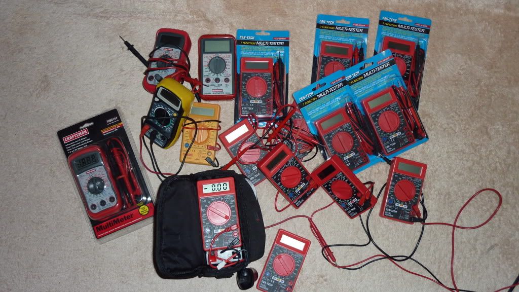
I use this same exact meter, works for me
BTW, I got mine at a Harbour Freight Grand opening - 99 cents. I bought 20 of them!
The electronics in them are good, it is the probes and switch that are of poor quaility.
If I have a problem (or the internal battery goes dead) I just open another!
at 99 cents I am able to use 3 or 4 at a time in a circuit. Also I have wired them into battery packs etc.
Heck the included 9 volt battery was worth 99 cents. Once in a while I still see them on sale for
1.99 or 2.99
Old-Lumen,
I can almost guarantee that your problem is a faulty test lead. As you know it takes a very good electrical
connection to pass the current required to run these high powered LED's. A bad connection in the lead of the
DVM would still be good enough the read voltage (very little current draw to the DVM) but not good enough
to pass current to "fire" the LED, hence the flickering LED. The leads included with this meter are junk.
For Current readings you should replace the wire and check that banana connector.
The nice thing about this meter is that the sockets light up for the proper leads and if you use the wrong holes it alarms and lets you know. It was set at A and the leads were in the proper locations. As far as the leads, these are about 14ga wire and the ends are soldered to them. The better style ends, not the cheap ones, like my first meter.