Newest results- positive
I powered up the heat sinked 7135 chips and got 1.4A to an XML so that part worked but when I hooked the chips up to the processor board I got all the modes but low but at very low output(~50mA). I ran some continuity test and measured 0 ohms between Vdd and ground. I believe the problem is on the board so I rather quickly set up a new board but keeping the 7135 chips on board and adding the 78L05 as described above leaving out the extra capacitors and it worked perfectly!
I was able to drive 3 xre-R2 in series with one Dx7612 1A multi mode board from 9s nimh 4/5 sub-c cells(12V no load). I started with a 1 ohm 2 1/4 W resistor to lower the voltage a bit and measured (under load):
Vbatt 11.38V
Vf all 3 LEDs 10.35
Iout Hi 1.028A Med 335mA Lo 64mA
Vout 78L05 5.02V
With this set up the chips were not warm to the touch and the resistor was quite hot. The board was not heat sinked in any way.
I swapped the 1 ohm for a .5 ohm 2W resistor and remeasured:
Vbatt 11.35V
Vf 10.35V
The other readings were unchanged but this time the resistor did not get warm but the chips did.
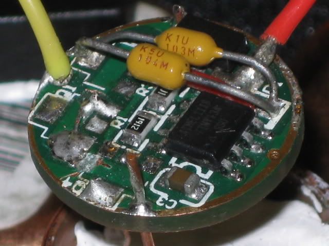
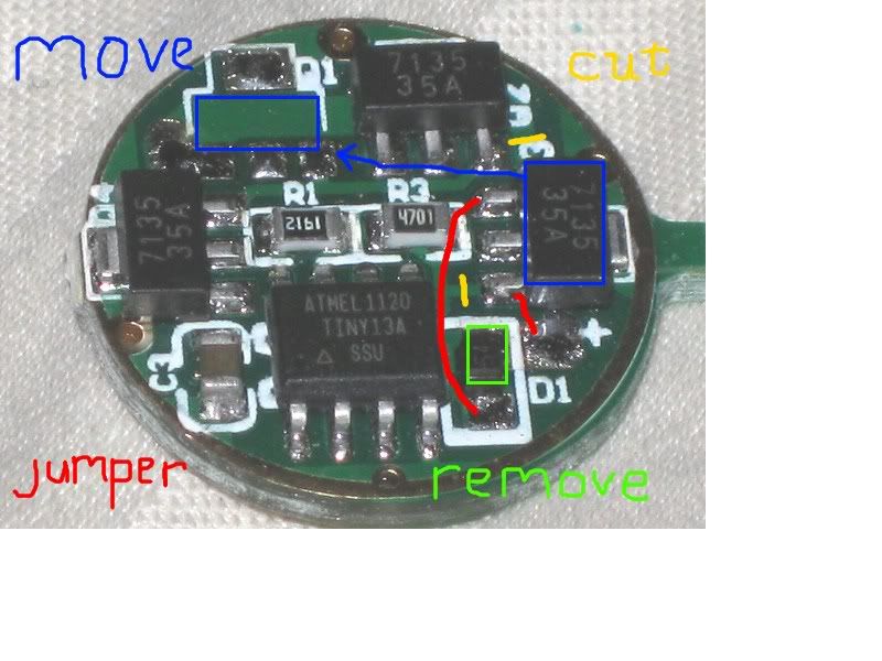
Making the changes to the board took me about 45 minutes and included removing and relocating 1 amc 7135 chip, cutting 2 traces, adding 1 78L05 voltage regulator(looks just like a 7135), and adding 2 jumpers for the Vin and Vout of the 78L05 chip.
If you have added or removed chips from this type of board then this is a pretty easy mod. I use a magnifying lamp and sharpen my 20W iron.
Next I will try this on a 105C 3A board with some xml’s.
So far it’s been a diary of ignorance, education, failure, and more recently, success. I think the various parts have been proven. Now I need to finish it off.
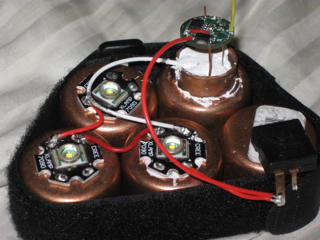
I rewired the sinked chips and added some more cu
and added the suggested capacitors from the L78L05 output to ground
wired it up to some xre’s
and got very little output. The modes worked except for low but high was only ~ 50mA(in that last pic I hadn’t yet moved L- to the 3rd led). I have not yet found the fault but when I connect the heat sinked slave to the processor board I measured 0 ohms across Vdd - Gnd.
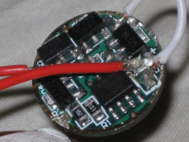
I know the slave works but to save time I did whip up a whole new board by just moving the 7135 closest to L+ to the empty spot on a 1A board to make room for the L78L05 voltage regulator chip. Before installing that chip I cut the Vdd and output traces that link those pads to the other 7135’s making sure to preserve the connection between those chips and the mcu. I also removed the input diode and added a solder link(under the red wire solder) to the input pin of the L78L05 and a jumper from the output pin to the Vin of the mcu(white wire). This time I left off the capacitors.
Using the same xre’s as before and powering them with 9s 4/5 subc nimh cells I first added a 1 ohm resistor to the positive connection and measured:
12V no load
11.35V under load at the battery
10.35V across the 3 leds
1.028A Hi
335 mA Med
64 mA Lo
5.02V Vout L78L05
The 1 ohm resistor was quite warm and the 7135 chips were cool.
I then swapped the 1ohm resistor for a .5 ohm resistor and repeated the meqasurements. They were all essentially the same only this time the 7135’s were warm and the .5 ohm resistor was not. A tactile verification of what the 7135 chips do.
So the idea works. I still want to see it function with the 7135 chips mounted on a separate sink to see how high they can be pushed above the Vf of the emitters. After that I want to try this out on a 105C driver with multiple xml’s.
What makes this work so nicely is the slick way the L78L05 voltage regulator replaces one of the 7135 chips. I would not have known about this chip without the help of DrJones and PilotPTK. Thank you both.
Here is an image of the changes I made to the board. The board has different resistors but the chip traces are equivalent.
The L78L05 replaces the 7135 chip that is moved. On a fully loaded board, the 7135 chip being moved would have to be stacked on another 7135 chip to maintain output. The resistor used between the battery and the leds has to be chosen based on the difference between the battery voltage and the Vf of the series leds and the max current being run. Lower Vf = Higher R value. The wattage of the resistor is chosen based on the voltage dropped across the resistor x Imax. In the example above, a 1 ohm resistor drops 1V at 1A and burns 1W excess power. This loss would occur in either a parallel or series circuit. An on-on-off switch can be used to transfer this loss back to the 7135’s when Vb drops enough for the excess voltage to be burned off by the 7135 chips alone. At even higher input voltages, an on-on-on-off switch(with 2 different value resistors) could be used to stage the voltage down. I have yet to determine at what point the resistors become necessary when the chips are mounted on a separate sink.
Nice research there Rufusbduck.
I think this is a very intelligent use of a common and useful driver to achieve the ability to run off higher voltages.
I havent tried to perfectly crunch the numbers as I’ve just read through the whole thing to be sure that I did not miss anything (or too much some might say )
But what I gather is that you will basically be able to feed 3 led’s off 1 driver at the cost of only 1 watt power loss to the resistor.
Just spitballing here but in a setup with triple XR-E driven at 1 amp with 3*3100 mAh capacity batteries that would cost you approximately 1 w for 2,5 hours or 2,5 watts total out of a power package of 3,1*3,9 ~ 12,1 watts or about 20%.
Adding to that the losses of the driver which are about 10% for this type as far as I remember then that is 0,1*(12,1-2,5)=0,96.
Total losses are then around 3,5W or 29%.
I am not familiar with multi emitter drivers at all but is that better or worse than drivers on the market or are you trying to achieve something totally different which I have completely missed?
I really dont mean to rain on your parade here, I am just not understanding what the benefit to this setup is?
The resistor is there to relieve the load on the 7135’s. Adding an on-on-off switch would allow the resistor to be removed from the circuit as Vbatt drops toward Vf. Post #24 shows (I hope) that the power loss in this application is virtually the same as in a parallel set up. The power loss will occur in either situation. Running series batteries, I needed to divert that loss away from the chips until the battery is partially depleted then switch out the resistor and let the chips handle the rest.
*
Also, I think you are adding a 10% loss that the resistor is taking care of. It’s not 1W in the resistor AND 1W in the 7135’s but 1W in the resistor OR 1W in the 7135’s.
*
I am not suggesting that this idea is in any way more(or less) efficient than any of the other methods of using these boards to drive multi emitters. It is a different way that allows series LEDs to be driven by series batteries. And don’t worry, I fully expected to have discussions and I brought my umbrella. In the example above with 3xre, the resistor may not be needed at all but it likely would be with lower Vf xpg’s and certainly would with 4/xpg/xml and 4 li-ion. The trick will be dialing in the resistance so that when the resistor is removed and the voltage jumps back up that it’s not too much for the 7135’s. That’s where a 3- stage switch might be needed. But as I said earlier, I hope to avoid that need with a dedicated chip heat sink.
And you may be right about the losses being too high in my run through. I am unsure if the 90% efficiency of the 7135 based drivers comes mainly from converting voltage to heat in the phase where the Vbatt is higher than the Vf of the led or if it more constant. Maybe someone more learned can chime in with their knowledge.
I think it was reading about these boards that originally brought me here but I’m neither an expert nor an EE. From what I understand the efficiency of them is based mainly on the ratio of Vout/Vin with a few microamps for each 7135 chip plus a few more for the mcu. The 10% is an average based on about 80% efficiency with a fully charged single cell and 1 led and approaching 100% when Vb = Vf. I am merely outsourcing the power loss until the battery voltage is lower. It’s there in either case(literally!).
In the case above:
10.35V / 12V = 86.25%(1.33V per cell, not fully topped off)
With 4 xpg with Vf total 4 x 3.3V = 13.2V
and 4 fully charged li-ion 4 x 4.2V = 16.8
13.2/16.8 = 78.6% with an initial excess of 3.6V.
At 1.4-1.5A that’s a total of ~5.4W or 1.3W+ per chip hence the resistor.
At 3.8V per cell = 15.2V, 86.8%, 2V excess, 3W or 750mW per chip… doable(I think)
At 3.4V per cell = 13.6V, 97%, .4V excess, .3W or 75mW per chip… not even warm
If that works then I don’t think xml’s will be a problem as even though the current is doubled, the number of chips dissapating the heat is doubled as well.
Something goofy going on. It works perfectly with the 7135 chips on the same board as the voltage regulator, or on a separate slave board, but not on the heat sink. I powered the heat sinked chips with a 12v battery and 4.5v across Vdd and it fired right up. I am going to try another dedicated sink. If that fails then I will have to see how well I can improve the performance of the boards with the chips mounted.
As I thought, the chips on the sink were adversely affected by a second reflow so I’m making another sink. I did successfully push 1.4A through 4 XML’s with 12V from 10 series nimh’s with all modes working. Higher current tests(3A) will wait on further sink tests. In the meantime, I have some more XML’s and an 18V Makita batteries that I can add to the 1.4A rig.
Thanks for that link Darkside. I’ve looked long and hard at that list over the last couple of years. Trying to find a small, inexpensive, relatively efficient driver is what led me to these 7135 boards. There have been so many great threads about them and I hope this mod can provide yet another option for using them. I spent last night and some more time this evening working on sink options for the chips. The space I have to work in is smaller than an egg and most of that is taken up by the led, led sink, optics, and switch
I’ve had success using taskled drivers but there just seems to be a different set of options with the 7135 chips.
Best of luck to you. Once upon a time, I tried exactly what you are after here, and personally came to the conclusion that it could not be done. My light was 5x MCE wired as 4p5s, powered from 16 Eneloop AA in series.
The problem as you have probably noted with using the Download method, where the mcu of the mode board is powered in series with the LEDs, is that on any single mode, you could negotiate the difference between the Vf of the emitters at the desired drive current, and the Vbatt under that load with a resistor of the proper value to burn off the excess and just feed the mcu a voltage that’s within it’s acceptable range. The problem with that design is that under different modes, the Vf of the emitters changes so drastically from one drive current to another that a single valued resistor ends up not leaving enough voltage for the mcu on high and way too much voltage on low. My mode board would either overheat nearly instantly on low or not operate at all.
In an attempt to uncouple Vin on the mode board from the Vf of the LEDs at various currents, I selected much higher valued resistors and fed the MCU directly from the switch instead of from the LED- of the N-1 LED. Among the resistors I had available to me (salvaged from parts discarded while modding) I recall finding that I still encountered the same problem as with the MCU in series with the LEDs… some times the light would light, but I couldn’t get the full range of modes from Low-High to work.
I think I theorized back then that full extent of the voltage sag between essentially open pack voltage on low and a 3A load on high, the 16AA pack sagged ~7V (from 23V open down to 16V under load on high) and that was just too much, what with the operating range of the MCU being only about half that (something like 2.5v-6V).
If only there were an easy way to change the value of the resistor responsible for stepping down input voltage to the MCU, as the modes change. It would require the lowest value on high mode and the highest value on low mode.
If you manage to discover an elegant way to do that, my old LED Ultra Stealth Light might finally get some modes after all.
So far using the 7805 regulator, I’ve been able to run a DX 7612 attiny board at 1.4A and get hi, med, low, strobe, and sos modes. Dr. Jones suggested that chip as a more viable alternative to resistors to control the input voltage to the processor for the very reasons you mentioned. Using that chip allows me to forgo using an led to drop the voltage in front of the board. The led’s are all in series together. V+ to led + to 7135’s to ground. The processor essentially runs on a separate circuit: V+ to 7805 to processor to Vdd 7135’s to ground. Any resistor needed would only affect the voltage to the high current side of the system as the 7805 would continue to feed the processor with the correct voltage. The 7805 chips are available on ebay and at mouser. Mouser even has a LDO version that would allow 2s2p setups with 2 li-ions and maintain voltage regulation down to 6V.
I would love to see this mod done in a flashlight as my motivation come from bike lighting where higher voltage is sometimes preferable to high current. Because of that I lack the specific knowledge that would apply to handheld lights. I expect there are some out there waiting for this to happen in a 4-D Mag but it won’t be me doing it.
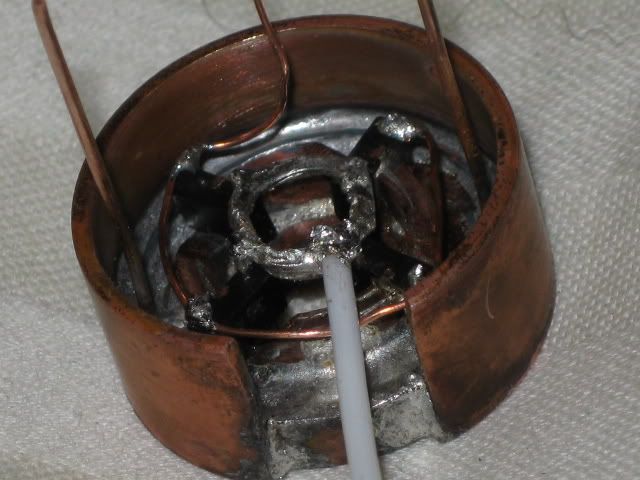
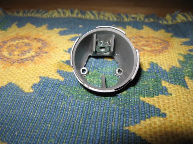
Since I was last at home and was able to verify the demise of the 7135 ships on the heat sink(not from over-voltage but from overheating during a second reflow), I did some work on a new heat sink. Of course, not being able to leave well enough alone, I changed it a bit and experimented with adding fins.
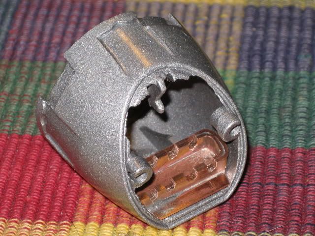
It’s a nifty little job but although it should be fine for multi-emitter optics it’s to big to use with an single XML in the lamp heads that I use so I made this one as well.
For scale the circular part of the first sink is the same size as a 17mm board and the two parallel rails on the second are ~ 9mm overall width x ~ 25mm long. Either sink would be connected through the shell to more cu exposed to moving air. The Ledil EVA tir optics I will use are 17mm deep and the aluminum shell is only 35mm long on the longer bottom side. The switch occupies the area above the centerline of the screw holes in the open back of the shell and rests on the aluminum “hook”.
One other thing I should mention is that with the 7135 chips removed, only about half of the board is still needed, allowing for further space economy(similar to the old pwm boards).
I like the way the fins turned out and will likely use that process to shed heat outside the shell. It was done be using a step drill to punch holes in thin(no idea what guage) copper sheet the size of the “pill”, and separating them with hoops of 24guage(?) solid cu wire. I coiled the wire around pipe a bit smaller than the pill and slipped the coil over the pill to measure and cut the hoops. I have access to a high output soldering iron so I may try to solder the chips onto one pill with that and attempt reflow again with the other. A realistic goal for these would be to burn off 2V over the combined Vf of the led’s anything above that would be gravy.
Yes, of course, how could I forget (I was actually nodding off at the keyboard last night when I wrote…), the problem of the voltage range isn’t only with the MCU but with the 7135s as well. It seems that’s what’s needed there is something like 7135s for the 7135s. I wonder if they can be run two in series, with the ground of the first connected to the LED- of the last, and the last’s ground connected to ground as usual (and the MCU connected to the VDD of all of them).