pics please ![]()
Just remember that your leads will have inductance, capacitance, and resistance. In many cases these things could mess up the results, that’s why the device is built the way it is rather than like a DMM.
In circuit testing can be pretty hit and miss. It really depends on how the circuit is laid out, but you’ll often find scenarios where you can’t measure things properly in-circuit. OTOH you’ll often find things you can measure in circuit, so don’t let me stop you - just be aware of what you are doing and whether other components may skew your results.
Will it throw it off “that much”
After all most other test equipment have pretty long leads as well…
Depends on what you’re testing, I dunno.
Depends upon what you are testing. Trying to measure a 30 pF cap with 200 pF of test leads or a 20 milliohm resistance with 1 ohm of test leads isn’t a good idea…
200 pF of test leads is nothing when measuring a 10 uF cao. 1 ohm of test leads is nothing compared to a 1k resistor…
So let me get this straight: I can stick a component anywhere in that ZIF socket, in any orientation, and it will tell me the pinouts? Would I have to worry about frying anything accidentally?
Do not expect that, it probably has 3 terminals it measures on.
In the supplied documentation it probably says how these 3 terminals is connected to the different pins in the ZIF socket.
This kind of tester uses a rather low current, i.e. the risk of frying something is very minor.
That’s pretty much how it works. The ZIF socket pins are labeled with 1-2-3 with multiple pins on the socket assigned to a 1/2/3. i.e. you can’t stick a device into two pins labeled “3”.
The max test current is 6 mA so no worries about frying anything.
I went to the local surplus store and tested a bunch of their devices. The only thing it has problems with is big triacs and SCRs that need more than 6 mA to turn on. Also inductors less than around 20 uH.
The perfect PolyPaks accessory!
Polypaks! Your advanced state of geezerdom is showing… young whippersnappers these days don’t know the simple pleasures of PolyPaks. I wonder how many floor sweeping brooms they went through?
Went ahead and ordered, said it could take as long oct 22 but I dont really have any immediate need for it so oh well, I’ll probably forget about it by the time it gets here and it’ll be a nice little toy.
WTF is a PolyPack? Google image returns a random assortment of not-even-remotely-related crap.
(You misspelled it)
texaspyro was right, you young whippersnapper!
They advertised their components as “untested” But of course they were already “BIN’d” The problem was it was the trash bin (Barrel)
They didn’t lie, here is an old ad for their “Barrel Kits” (the barrels were not make of wood though) ![]()
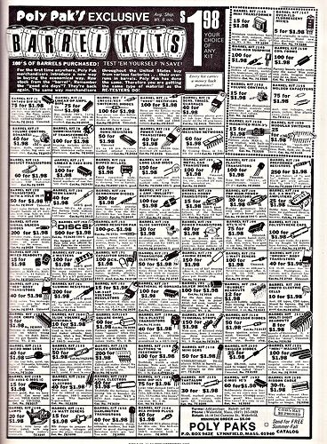
They bought surplus crap and floor sweepings by the barrel full and resold them in little plastic baggies…

Lol thanks guys.
So I got mine yesterday, in reference to your mod in post 14, sounds simple enough I should be able to figure it out but just in case is there a diagram / labeled pic somewhere to show me what parts / pins / traces are what?
Will you please review it for us? I am really intrigued by this device.
I could do tha however I don’t have that large a selection or parts to test, would you (or anyone else) be willing to mail me a selection of different components (I’ve got resistors and diodes covered, what I could use are SCR’s, inducers and large (2000-200,000uf [the claimed limit]) cap’s
I sure would!, I have thousands of older discrete components.
PM me with your address
Haven’t ordered this tester yet? Stop fighting the impulse… it’s the right thing to do ![]()
I’d have picked one of these up by now but for the ridiculous excess of options, and not knowing which ones will be upgradeable as the firmware continues to improve. The eevblog thread on them isn’t much help either.
Got busted electronics…and a hot air gun? You have TON’s of random parts ![]()