I should be getting my package by next Monday. It just processed through San Francisco. Usually takes 3-4 days after that for delivery. Looking forward to another nice Reylight to be added to my collection.
With that tailcap switch, is there parasitic drain?
The Ti Tool arrived this afternoon. Thank you Rey. This is a killer-light, not just some stocking filler. I bought it for the birthday of my better half. With her name on the bezel and the bunny wabbit logo on the tube, she just has to like it.
Or else … stay on the Dark Side for the rest of our lives.
Like the others reporting in, I have to agree this is a fantastic light! The switch is really slick - perfect feel to it. The tint is nice. The heft and weight with an Eneloop installed is just right.
I have not taken it apart yet to see what the brass pill looks like. Anybody have pictures?
Also, like @ohaya, I was wondering about parasitic drain.
Mine arrived today and it’s a sweet one. A really classy little light for sure. Brightness is just as expected with perfect tint for me. I’m really glad I got in on this buy.
Thanks for this!
Mine also arrived today - very nice! I like the switch so far, but the dbl-click is just another way of saying: click twice to change modes -> OFF then ON. So from OFF, it takes 5 clicks to get to hi. There's no memory, so it always starts on lo. It seems to be the same driver as the ReyLight copper tool, but since the copper tool has a std clicky, you can do simple 1/2 clicks to change modes, so it's much quicker to get to hi (click ON, then 2 1/2 clicks).
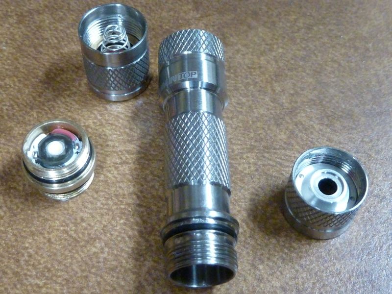
Of course I took some output measurements and dis-assembly pics.
On a fresh Amazon Basic AAA primary cell @1.61v: Lumens: Lo: 0.8, Med: 19, Hi: 81
On a Eneloop NiMH fresh off the charger @1.51v: Lumens: Lo: 0.5, Med: 19, Hi: 80
This is pretty much dead-on to what was posted.
My modded/upgraded copper Tool (mods: 219C 4000 on 10 mm SinkPAD, 26 AWG wires) on same Eneloop NiMH @1.51v:
Lumens: Lo: 7, Med: 31, Hi: 103
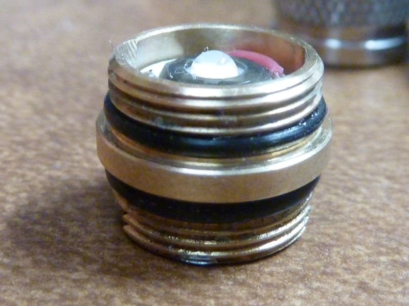
There did appear to be some glue (or something) on the brass pill body tube threads. It took sticky gloves to break the binding on those threads - little tough, but not too bad.
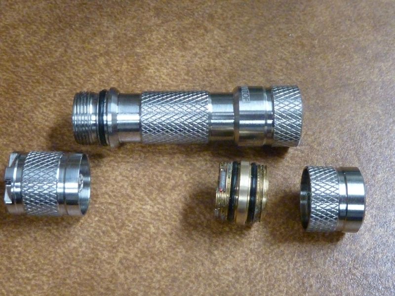
Here's the pics, tried not to duplicate ones already posted:
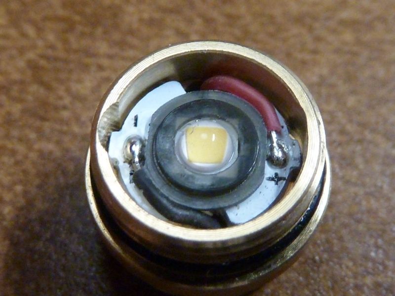
Here's a shot of the stock copper tool pill parts, and showing the new 26 AWG wires and SinkPAD:
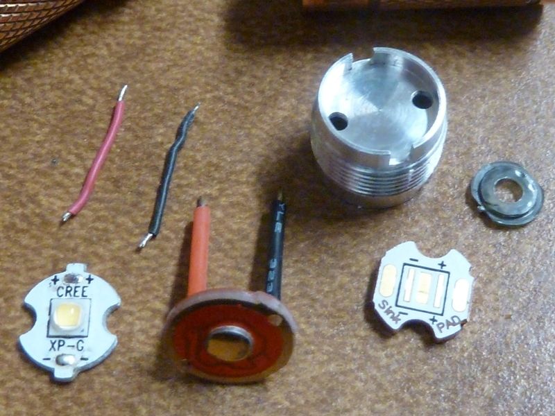
It's not too bad to swap LED's. The 10 mm SinkPAD would probably need to be sanded down a bit because it's thicker than the stock one, and that extra height might cause the bezel from threading all the way down. I didn't do this though on the copper tool. Notice the driver is solder to the brass pill in 2 spots on the edges. Don't think the copper tool's driver was soldered - might be needed though in this light for a good ground.
Thanks for the quick tear down Tom, I was most intrigued by how the switch works. So it is actually some kind of electronic relay switch?
Didn’t get into yet, but it behaves exactly like a power switch w/OTC, so I strongly suspect it’s not electronic at all. Also it’s the same driver as the clicky switch copper tool, accept they made the lo modes more like a moon. Maybe they located a cap at the tail instead of on the driver, but the behavior sure is the same. Didn’t measure it (dang I could easy), but doubt there’s any parasitic drain.
The behavior is not as nice as a regular clicky because there’s no 1/2 click, so you have to do 2 regular clicks to change modes, but it’s easier/shorter press than a clicky.
![]() Thanks for the nice work.
Thanks for the nice work.
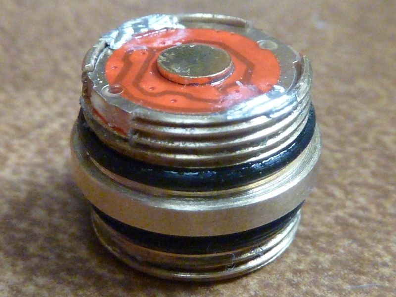
Look’n a bit more, I couldn’t get the retainer ring in the tailcap loose - may need more work. But you can see a SMD part on the spring contact board - not a cap per say, but maybe a diode, not sure.
Tom. You went from 0.5 to 7 lumens on low mode by swapping wires and the LED?
It is a normal retainer ring, just much smaller. And it is not glued either. Just a rather sticky lube, so you can not yank it loose in one move. You have to apply constant pressure and it will come out. BTW, I use a (one) piercer to do the job. The inside of the switch has an electronic board. The macro-abilities of my camera(s) are not the best, but at 11 o’clock you see a smd-switch and at 7 o’clock you see a small battery. The picture I took is not the sharpest so I did not shrink it.
Don't think I took measurements on the stock copper tool (least can't find it), but it was supposed to have a 1 lumen lo (moon) mode, so yes - that probably happened from the wires and 219C/SinkPAD upgrade. Possible my using a Li-ion might have busted something as well. The copper tool doesn't like a Li-ion cell anymore - loses modes. Probably caused by the bigger wires, not sure.
The switch is definitely "smart" from the pic above, but to the driver, it may be acting as a power switch - not sure. The driver definitely behaves like a power switch - this is why the dbl-clicks are needed to change modes. My thinking is all the components are there to convert the standard electronic switch to a power switch.
Hope this is understandable. A true electronic switch is monitored by the MCU, and doesn't shut off the MCU when the switch is dis-engaged. This all could be probably proven on the bench.
Mine arrived yesterday. A couple of things:
1) As you said, it started working after leaving a AAA Duraloop in it. Before that there was no light. But I thought this was 3 modes? So far, it looks like only 2 modes?
2) I did not get a keychain and also no O-rings in the box. Just the light and the clip (in a bag), all inside the box.
Please advise.
EDIT: Actually, there may be 3 modes, but the medium and high are almost the same brightness?
EDIT 2: I asked earlier: Is there parasitic drain because the switch? But it doesn’t do lockout because it’s not anodized?
The keychain and O-rings in mine were under the flashlight, under the cardboard/paddding thing.
Just tried measuring parasitic drain and saw nothing, as I thought I would. I jumpered the batt- to the tail spring, then put the DMM probes on the body tube and tailswitch ground, to close the circuit. If the MCU was running, I’d think it would show up. I’ve been measuring parasitic drain, and tailcap LED amps this way and it’s been working well.
I still can’t get off the tailcap retainer ring - came close to damaging my SS tweezers. Holes are just slightly too small for smallest tip needlenose. I’d have to drill out the holes to have a chance.
Nice shot though of the smart switch. Thanks! ![]()
Wasn’t MattAus working on a switch like that a while back? Does anyone else have this? I don’t recall seeing one before but the way my memory works that means not much at all. I know I don’t have one already, so it’s pretty cool looking to me. I have a Cu Tool and a Ti Tool en-route. ![]()
Hi Tom,
Ok, thanks for checking and for info about the keychain and O-rings! Maybe that (the no parasitic) is why it needs a double-click, i.e., maybe the 1st click activates it, then the 2nd one is what works?
Maybe that is what they patented?
Jim
Well got a USPS update that my lights are in Chicago, can’t wait.
However, I bought Reys first of all because it’s Rey’s GB and it’s a good price, but being I had already had bought one and knowing I have more on the way, I decided to see if I could get that light and that stupid switch apart.
Honestly if there’s one part of that light I can not stand it’s that switch, just junk, patented or not, it doesn’t work good at all IMHO.
So keeping my mouth shut for a change I started work on the light I had and right after I got my order in with Rey for a couple more and last night about midnight I finally had complete success with the switch tear down and though the head was easily disassembled almost immediately back when this GB started and it was heavily glued, the tail switch was a bear and I have been trying to figure out how to disassemble that thing and not destroy it.
It was very very difficult but I got it and I took a bunch of pics if anyone has any interest in what that battery in the switch and the rest of the junk looks like.
By the way, in an email Rey told me that he was going to try and see if the company would do Rey a favor and NOT glue this light, much like Rey did with the last Cu Tool GB,
I sure hope Rey had success because it is not even fun at all trying to take that switch apart with the glue Lumintop uses, it’s some good glue I’ll say that much…
Hardest part really is figuring out what kind of tool can I make that will get down in their to that retainer ring, well finally figured that out but that took the longest…
But don’t ever tell me you have a patented switch and then glue it together so maybe I won’t be able to take a look and see what so special, Ha Ha :smiling_imp: … BLFer’s Strike again…
I’m looking at these other Tools I have and the switches are pretty good, but I’m wondering if anyone recalls, wasn’t the switch in the Cu something special that Rey came up with or maybe I’m thinking driver, with low low nice spacing?
I love that switch but still someday want to do something about that rubber boot, and Reys Custom Cu Tool it’s still sitting here getting it’s patina and working great.
Edit: Well darn, I was so happy with my success I didn’t look UP the post and see that either someone has beat me to the bunch as usual or maybe Rey was successful in getting these lights unglued
I will go now and read what is the scoop up up the posts, DARN IT… argh and I was so happy with myself, just had to come over and tell everyone about my success… bummer ha ha ha
Say Tom, hey maybe my success at disassembly is still in play, I will post you some pics later of what I did to get that apart, I bent hardened steel trying to get that retainer, even after I took a hand drill and sized the holes a little larger, I’ll have to show you the bits I used and a pair of weird style vise grips and mini bench vise, and mine was seriously glued in. So Rey didn’t talk Lumintop into not gluing these I’m starting to think?
Have to go pray for forgiveness so will post pictures later if wanted, if not needed let me know and won’t bother, probably have it figured out before I get back anyhow…
Friend called and said she’s sick, so uploading switch pics,


Hey, Please tell me if posting pics like this one at a time, if it’s screwing anything up, I am notorious for that, if I should start a new post and just wait until I have all pics uploaded to host site, please let me know, Thanks
Sounds like there are variations of the glue - some tighter, some looser. Sometimes they don’t glue them all, just ones they think are loose. If you got detailed pics of the switch board, that would help. With this smart switch, think’n might not be good to do a FET DD driver upgrade - dunno if it can handle high amps. But really for such a small Ti light, might not be a good idea anyways.