Are there all the connection wires must be through holes ? If not, is it beneficial to change the bottom layer as ground and use thermal vaises to transfer the heat of all the amc7135 to the bottom layer and then to the bike light body.
Microa is correct. The current thermal vias are not achieving anything. Also they should be tented, IMO.
No, keep them open… you can then get some air convection through them.
V0.3 https://oshpark.com/shared_projects/DPOYmZL2
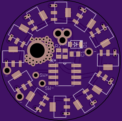
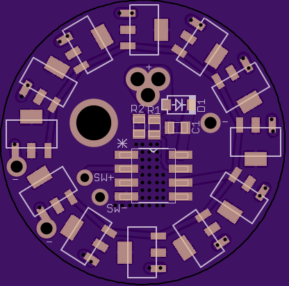
Edit: Here's a new version with a better thermal setup. Also all traces other than LED out are on the top (why the voltage divider is moved) and the entire bottom of the board is a GND plain along with the via's under the MCU.
Eh, now I remember mattthemuppet asking for “thermal vias” to link the ATtiny25 better to the heatsink. I’d forgotten that.
awesome! I couldn’t tell you whether or not V4 is better than V3, but it looks a lot nicer ![]() I think that has everything I could wish for in a driver and I can’t think of anything else - there’s plenty of space around all the wire holes and there’s now a nice clear path for a pedestal underneath the ATtiny and the mounting hole too, which is an added bonus.
I think that has everything I could wish for in a driver and I can’t think of anything else - there’s plenty of space around all the wire holes and there’s now a nice clear path for a pedestal underneath the ATtiny and the mounting hole too, which is an added bonus.
Just to double check before ordering some - will this board layout work fine with ATtiny25/45 that have the same footprint as the ATtiny13A SSU on the Nanjg boards?
Also, do you mind me sharing your work and the OSHpark link with others, crediting you as the designer? There may be people on the DIY bike light forum that would be interested in this.
Wight - you’re right, it’s about a better thermal coupling between the driver and housing for temperature sensing
I’m not sure that those vias are going to do much for you, but then again I could be wrong. Much better to use a remote probe IMO. Note that a remote temp sensor was recently discussed (and implemented) in the last ~10 pages of the STAR firmware thread.
You’ll machine a pedestal for this driver to sit on so that stuff does not short?
thanks for the input wight - a remote prob would be cool, but the discussion on the STAR firmware thread went waaaay over my head, so I think that the onboard Attiny 25 temp sensor will have to do. It's the simplest option both from programming and board design perspectives. It's not going to give a close reading of the housing (or by extension, LED) temp, but I can use some broad fudge factors to set the temp response at an appropriate level. From memory, my Taskled lights where the drivers are similarly thermally coupled (couple with JB weld, another with thermal tape) have the step down set at 60C. Assuming there's at least a 10C drop between substrate and star, then star and housing, then housing and driver, that should put the LED substrate at ~90C, which is within reasonable limits of what they can handle. It's not very precise, but it works pretty well and I can always tweak the threshold value a bit.
yup, pedestal will be machined. Haven't worked out the housing design in detail yet, but it should be straightforward to take into account when I'm milling out the driver cavity.
I agree that the internal temp sensor will get you quite a ways. Some fudging to get in the ballpark and it’s way better than nothing!
you're right, it's really just a basic protection mechanism at the end of the day in case it switches on in my bag or I leave it on full after stopping on the trail, so precision isn't really necessary (compared with voltage monitoring, for example!).
Just ordered 3, now I have to wait!
thanks again CerealKiller, I owe you one :D
well, it’s only been 4 years, but time to say a BIG THANK YOU TO CEREAL KILLER yet again!
Just finished up a new light with his driver board
full build thread
http://bbs.homeshopmachinist.net/threads/77248-All-in-one-LED-bike-light-for-my-commuter
As to the driver board, everything other than the programming went well. A few remarks relevant to earlier discussion:
1. the driver was mounted on a tapped post with a M3.5 screw, so it was thermally connected to the light cover but there was no risk of any shorts
2. thermally it appears very impressive as some of the wires were a complete pain to solder. Had to turn my iron up to “soldering well screwed down copper stars” power levels
3. through holes could have been a wee bit bigger for the switch wires, simply as I was using the same AWG wire for all of the contacts so I could connect the driver and the light using a JST plug
Again, I’m pleased as punch and can’t thank Cereal Killer enough. If you ever need something machining or anodising, let me know!
I have a couple more lights on the mental drawing board (dual LED helmet light and a dual LED bar light for my mountain bike) that will use these boards. For those I want to work on getting an available ATtiny25 firmware with temp control working the way I like it first as those will be more challenging lights from a thermal perspective.
WOW!!! Holy smokes…what a great build and TON of awesome machining…very very cool!
Wow Matt! Nice work! BTW - I see you’ve moved to Texas now. Boy, you do get around!
-Garry
thanks guys! My skills and tools have improved alot in the last few years, that’s for sure ![]() Still screwed up a few things but nothing too major. It was easily my most complicated milling project so far and it came out pretty much as planned, which is neat. Next major challenge is learning Fusion 360 so I can start using my 3D printer to its full potential!
Still screwed up a few things but nothing too major. It was easily my most complicated milling project so far and it came out pretty much as planned, which is neat. Next major challenge is learning Fusion 360 so I can start using my 3D printer to its full potential!
Garry, yep, moved down to San Antonio from Washington state last year. Hopefully not moving again for many years. That was also what helped me get the mill (a 6x26 Grizzly knee mill) which has made all the difference to my machining capabilities. It’s really impressive how quickly it can turn a lump of aluminium into chips.