Please stick to what I said. These pictures are not my pictures, and the reason I linked them is because they clearly show the relative size and location of the sense resistors. Period.
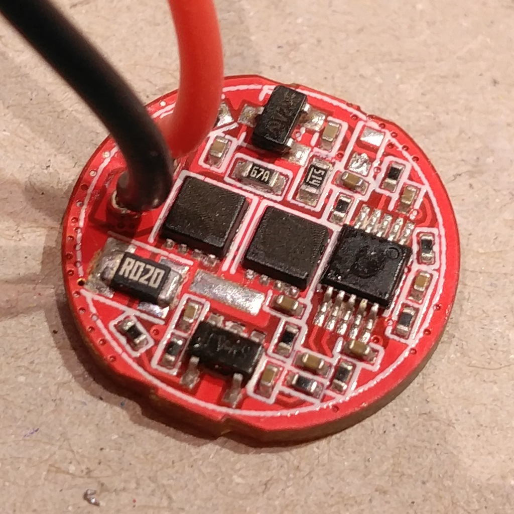
Note what I said above. I've only seen ∅17mm drivers, they use 1210 imperial size resistors; the ∅20mm driver looks to use the same size. The ∅22mm driver looks like it uses a bigger resistor, 2010 imperial I'd say.
I never said you need to remove thermal throttling. Me and others do, but if you feel better leaving thermal control then do so.
Everything is crystal clear. What has been said: swap the sense resistor stack. Decide what maximum current do you want, and then calculate the required sense resistor value.
Not to seem like Mr Glass Half Empty, but if you’re not at least reasonably sure what to do (and why), you probably don’t want to monkey with a light unless you’re willing to take the risk of ruining it.
Okay everyone, stop, no more attacks. It doesn’t get anything resolved.
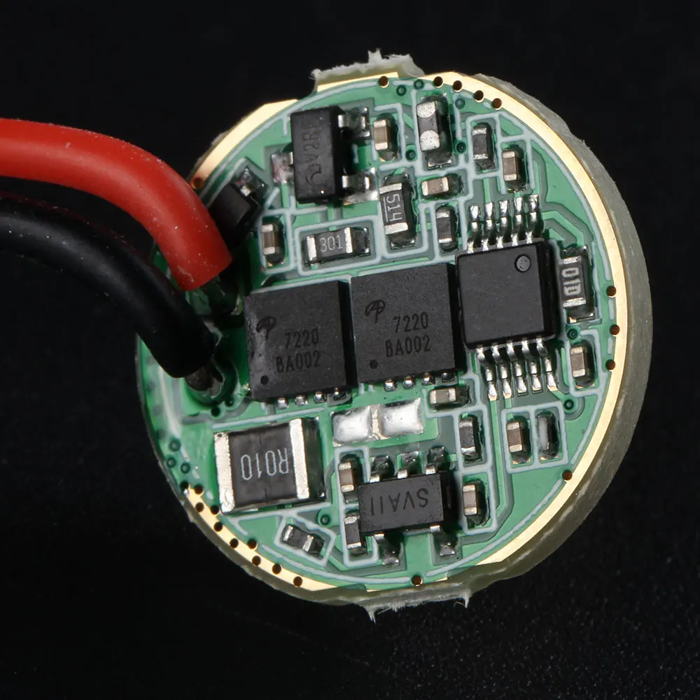
Musaka, Barkuti referenced a thread where the thermal sensor was discussed, but in that thread were measurements for the other resistor, the one that controls current. On the 17 and 20mm drivers they’re 1210, and on the 22mm (which is the one I currently have and have tested on), it’s the 2010.
Hope that clears everything up, and let’s all move on without any more name calling.
Yokiamy, calm down; I did what it had to be done, report sb56637 what was happening. This was a good deal of hours ago, when Musaka Despa started blatantly trolling on me (again). I never insulted him, he was lying. And in case any of you is wondering why do I say “again”, is because Musaka Despa is the same guy who started misbehaving in this same thread two weeks ago under the nickname Bison Jack (banned). So Musaka Despa was banned, again.
Nothing blocks him from re-registering a new account and coming back here. If it happens, good luck and deal with him.
The first one is personal and minor, I purchased and received an M2 host from Simon recently and finally got to build a torch with it. A problem I found is that the holes for the driver/emitter wires were not in the right place for MCPCBs from Kaidomain, and I've been forced to mill my CSLNM1.TG emitter MCPCB from Kaidomain for it to fit. Now I realize that the KDLITKER MCPCBs are not using standard 60° hole spacing. There was a tiny misalignment, though.
I also found that, after screwing down the bolts, they started topping at the outer black rim in the M2 cavity before pressing down the MCPCB. I added some Stars-922 thermal glue around the bolts to sort of fix this, and also ended up screwing them down as much as I could. Still I wonder if this is normal… :???:
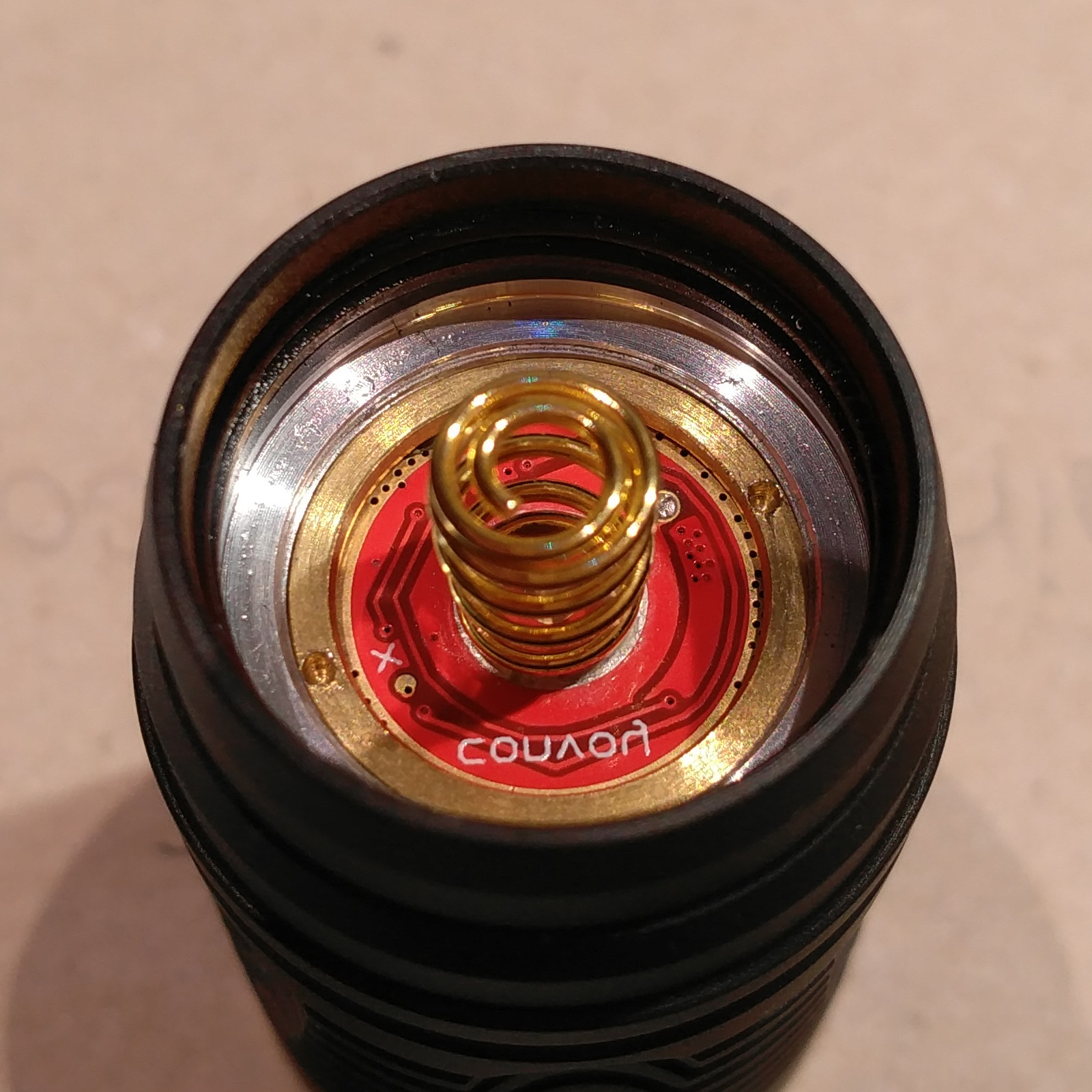
The other issue is related to the newer design of the SST-40 linear drivers. As you can see in the left photo, drivers do not have an electrically conducting outer track on the upper side. This, combined with the shape of the retaining ring in the M2, results in the driver hardly or not making electrical contact with the flashlight body. I also wonder about the thermal transfer due to the absence of the upper side outer track (solder mask covered).
I feel pretty dissappointed right now. I've spent a good deal of hours with this because at first I couldn't realize the driver thing was the problem. I think I could fix the problem by tucking solder paste on the bottom side outer track, and applying heat with my hot air gun. But I have mixed feelings about all of this, suffice to say.
The missing contact ring track or ground ring track is that in the driver's front or upper side, at least as far as I know or understand these things. The back or bottom side is where the spring dwells.
I have a couple drivers and as you can see in my picture, I removed the NTC thermistors.
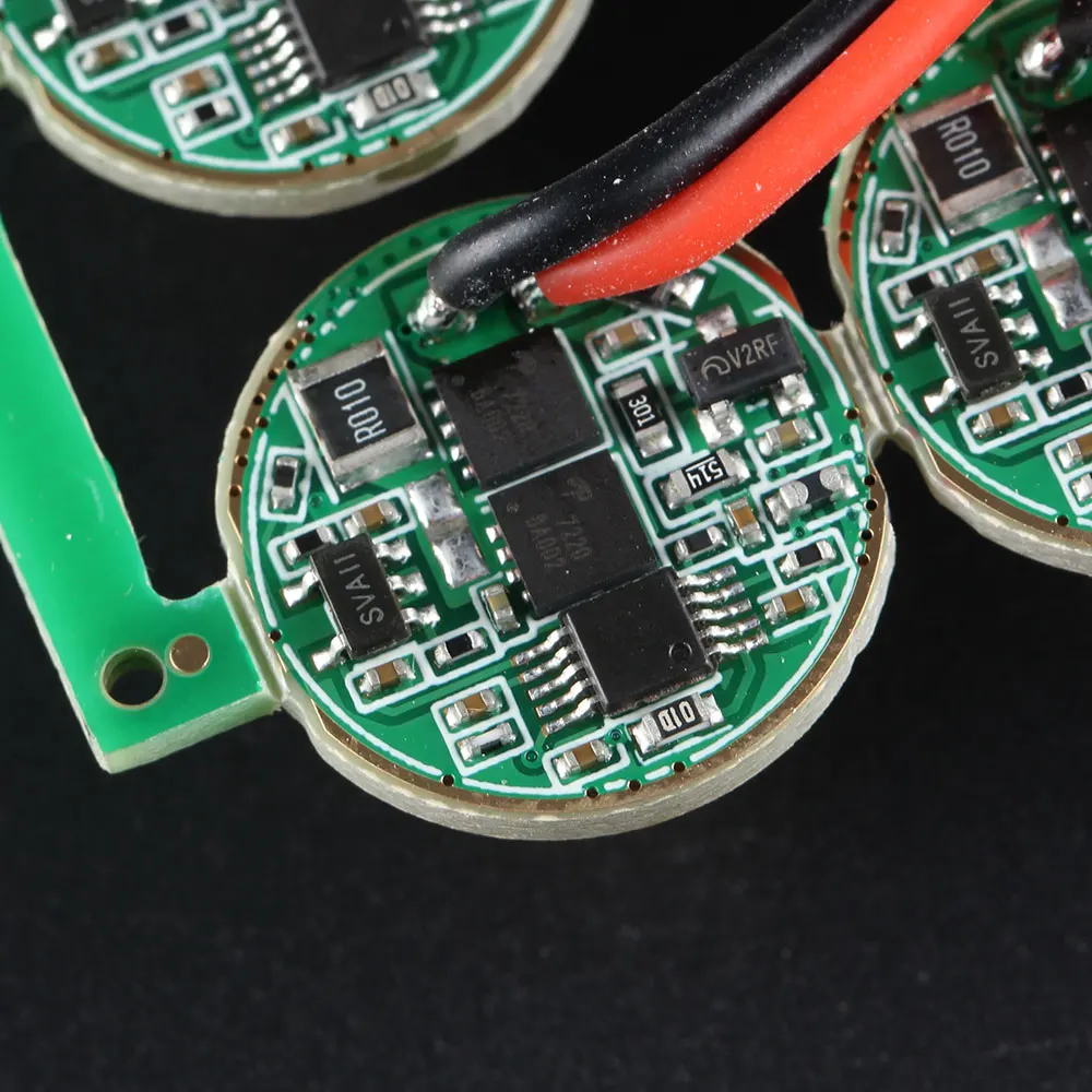
Notice the presence of an outer ground ring track in the green solder masked 4-mode drivers.
Without temperature protection I can only rely on good thermal transfer for my driver to work properly. But these drivers don't have upper or component side ground ring so, unless I am missing something, their life is gonna be rather short because of overheating. :???:
I am feeling rather uncomfortable at this right now.
Still, I have to come back and pinpoint this. My M2 build cannot work this way. The retaining ring has a sloped inner surface ring on the side which is in contact with the driver, and a small flat outer surface ring (which makes no contact with the driver unless I were to forcefully slip it). As it is, I can only make it work reliably by soldering the retaining ring to the driver. And I defitively don't want to resort to that!
Will wait for Simon to see what he has to say. I think I'll have to order a set of 4-mode drivers (drivers with a working, solder mask free outer ground ring in the component side), which even if I get some refund is going to be :(( another long wait.
Is it possible to use by flip’n the retaining ring over, file 2 slots in it for tightening with needle nose pliers. I have wire gauge drills that in this case I would just drill thru the holes in the retaining ring, deburr and use the other side of the ring…
I tried this with my C8 when I got the new “biscotti” driver. It didn’t work with the retainer the right side, so I flipped it and got the light to work for a few seconds then it killed the led and smoked the driver…something wasn’t happy with the setup! Maybe a short? I never figured out what happened.