I did. That was all I did to it. Worked beforehand. I wanted 18ga leads too. Same as your pic too, just a tiny bit of the triangle pad remaining around the hole.
If I’m looking at things correctly, drilling out the center hole actually broke the main positive connection to the side of the board with all of the components. I believe that hole was a big “via” and was lined with copper to power the circuitry (yes it’s connected to the main LED, but you also need Pos on the driver to run the IC and such). There is one small remaining via next to R1, but you’ve cut off the blood flow to the LDO.
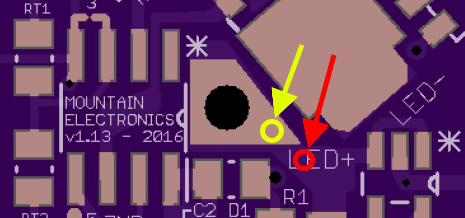
I’ve never tried this, but in theory you could probably try to create your own via. Drill a small hole in one of these two places - preferably the yellow if there is room, the red might get too close to the outside of the positive pad on the spring side, you wouldn’t want to miss and cut the trace that’s over there. If you drill at the red circle, carefully scrape a little ring of solder mask away around the hole to reveal some copper for solder to join to. Prep the hole and surrounding area with a little flux, then fill the hole with solder. It might help to hold a small wire (with flux on it) in the hole to provide a path for the solder to easily follow, but then you’d need to carefully trim the wire down. It might help to temporarily remove the negative lead (or perhaps both if you’re comfortable with that) to give you ample room to work with.
try this at your own risk… I take no responsibility if your already non-functioning driver becomes even more non-functioning
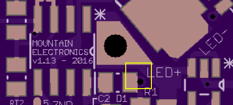
I would guess that you could also just try to connect to the existing via instead of drilling a new one; it’s not very big but I doubt that much juice is needed. Try bridging from the via next to R1 or the pad connected to it over to the main pour coming from the Pos hole. I think that should do the trick.
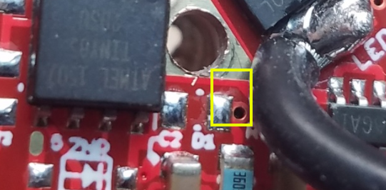
gchart. Thanks for all the help! It’s pretty amazing you know what all of these things mean on these boards :+1: I managed to jump that R1 pad to the main hole, and it turns on. The UI is pretty weird though. At first it was flickering when on low, now it turns itself on on low whenever I give it power (click the tailcap.) It ramps, but every now and then it won’t respond.
Pretty sure the driver it shot. For $12 I’m just going to order another one from MtnElectronics and be done with it. Which, on that note, I really like the OP reflector and the XHP70 beam… is there any reason to jump over to the XHP70.2?
Like I told you before, put some solder paste on the lead from the spring side and solder it in from there, or alternatively strip a ring off the lead close to the board and solder it to the pad. When you drilled the hole larger you removed the contact between the pad and the spring side so the MCU is not getting power, use the wire itself to do the via’s job and get power to the MCU
This is why I don’t care for these driver types, I like to use heavy leads and the via approach is a limiting factor. I normally just dolder the big wire into the via then do an independent spring bypass.
It turns on, but the UI is really weird. When I turn the tailcap on, the light turns on (its suspended to turn on with the side switch like the D4). Sometimes it’ll ramp, sometimes it has set modes it likes to go through. :person_facepalming:
Solder your + led lead to the board making sure enough shielding is striped so you have enough wire to go through to the spring side and be pretty flush with that side. Make sure solder is built up and covering the pad on the led + lead side and the spring side. Get rid of the jumper solder from before. Then do a short spring side bypass. 20AWG is good enough for the short spring bypass. If it’s still acting up then look (with a magnifying glass) for shorts on any other components. If no obvious shorts are found then just cook it (reflow it) by whatever means you can come up with. (Remove the spring and lay it on some aluminium foil in a pan and put it on the stove at around med high heat and watch it till the solder liquifies then remove from heat. If you have flux use it liberally. Once it’s reflowed then clean it with acetone or alcohol and acid brush. Inspect with magnifying glass again for solder balls and shorts. Remove solder balls and shorts. Make up some test leads with small magnets and alligator clips. Test the setup outside the host before installing into said host. If it still doesn’t work then send it back and give Richard whatever he asks to fix it.
I’ve seen a formula of 0.22/sense resistor = output for a 6V emitter, so if you used a R050 it should be around 4.4A, an R060 would be around 3.6A. This is guesstimating and coming from me so you should probably check it.
Just to be clear, DB is saying remove the pair of R082 (making 0.041 ohms) and put in its place a single R050.
I think his numbers sound about right. The amp draw can also vary based on what batteries you use so you might have to get a few different values (R045, R050, R055, R060) and actually try them out.
If this formula holds true for this driver then the .041 resistance should be netting around 5.36A, is this the case? (An R056 should get you in the ball park of your 4A target…)
As you can see here though, it doesn’t take a lot of difference in the sense resistor to make a fairly large impact on the output current. Make small changes, in other words…