Subscribing. I know I’ve been MIA for a long, long while… But both of my modded Y3’s drivers are halfway dead (one running an xml2, one running an mtg2). Starting to miss having them operational, so I reckon I may be getting some of these to build.
Welcome Back! Wondering what your driver problems are. I've seen the switch get bent back on one heavily used Y3 - had to fix it up. With DEL's driver we can use a better quality switch, plus beef it up to have more rigid support.
Apologize in advance for the thread-jack… With both the first issue to pop up was the low voltage step down started kicking in earlier and earlier. The mtg2 would start flashing after less than 5 min on fully-charged batteries. Then it quit driving full power to the LED and now operates on probably 1/4 of normal power levels on all modes, regardless of battery voltage. I haven’t measured it to see exactly what it’s outputting to the LED. The Y3 I have with an xml2 does the same thing, but it started after it got dropped one time. It also did the LVP drop prematurely as well. Both drivers are resistor modded. Can’t remember what values off the top of my head.
DEL - I added a C3 equivalent to my 16X XHP50 light. Used a 4.7 uF cap between the Batt+ and ground ring on the batt contact side of the driver. It seems the 7135 is a lot more stable now - works in ramping and mode sets. I had to crank up moon mode to PWM value of 7 on the 7135 to be visible, and it's barely visible.
The blinking I do for configuration settings might be a bit flaky - usually works but I've seen it not work once. Been wanting to try this for a while now. Just got notice those new Y3 LDO drivers just shipped.
I do not have any DIY 2S lights, but I still want mock one up to see what is happening. When there is significant wiring between the 7135s and the LEDs, the datasheet also recommends a 0.1 to 1 uF bypass capacitor on the output side of the 7135s, in addition to this C3. But of course we want to be able to PWM the 7135s and FET, which the datasheet does not consider.
I dunno how many amps - no way to measure it right now. Gotta rig up something for my clamp meter, just haven't had the time. Think'n with some cuts & jumpers I could rig up the tail PCB, like I've done in SRK's. Maybe have a short 14 AWG wire in normally, than swap it out for a long one to clamp around. It's a 3Px2S SRK style, meaning no battery carriers, cut out holes for the batteries, so the tail PCB w/springs is very similar to SRK's, but only 3 springs.
For the XHP50's, 2.5A each is 40A, 3A each is 48A, so sure is possible.
More I think bout it, probably better to re-wire the tail PCB anyway - need to go with heavier gauge wires all around because this current has got to be crazy!
DEL - I received the Yezl Y3 LDO board, but of course, no time right now to try them.
But what would you expect to see for parasitic drain with the LDO setup? I'm asking because I have a TA triple with the same LDO in a Convoy L6. Found the L6 with dead cells. So popped in charged cells and see a parasitic drain of 3 mA, which seems pretty high. Maybe I don't have the rest of the circuitry done correctly?
I used a 10 uF cap for C2, as TA recommended. Does this 3 mA sound normal or is something not right?
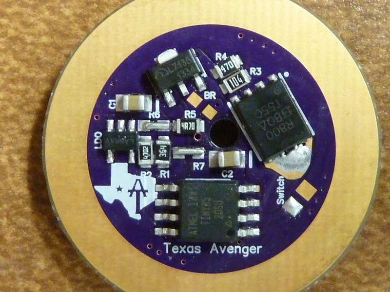
This was with the MIC5235? It is meant for battery applications, datasheet says 18 uA ground current under no-load. Add another ~20 uA for the driver and we should be at 40 uA or less.
I re-tested on fresh cells and got 4.7 mA. The big 16X light using Harley's board measured at 0.56 mA.
Yes - both use the MIC5235-5. Hhhmmm. Well, I can see much higher amps for a few secs before it drops -- that's me though, think I delay 5-6 secs before sleep. Also I'm using 360K/47K voltage divider resistors so that should help reduce the drain too.
Would the cap setup and values possibly make the drain worse? Maybe I got something wrong there?
The TA board does not seem to have the correct LDO…Marking is off?
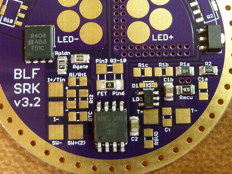
The LDO marking on the HQ board is spot-on, but drain seems too high as well. Should be about 50 uA with BOD on and those R1, R2 values. Firmware is sleeping all the peripherals?
Caps should not contribute to drain. Maybe if they are not rated for the voltage?
These have both suspect 7135s…no hint of light when off?
Ooops, wait - think that picture was taken before swapping the LDO. Originally I used the wrong one. I checked the LDO last nght and it had the same marking, L250, as the 16X.
Ahhh - suspect 7135s? I don't understand. These are the same 7135's I've been using all along - from Fasttech.
No - don't think they've shown hints of being on. Sorry, can't check the L6 this morning - no access. Maybe that's the problem...
AFAIK you use the ‘good’ ‘saber-tooth’ type 7135s. But you had stability issues in the 2S lights with them. They may be damaged?
Re. the new C3, as per PM it tested as expected. So worthwhile to add on hi-power or 2S builds. I also tested a C4, going from L- to ground, as per the 7135 datasheet. I used the recommended 0.1 uF. This too gave a nice improvement to the noise seen on the switching node (L-/FETdrain/ 7135out). It had surprisingly little effect to the switching of either the FET or the 7135. Basically just acting like a snubber at the relatively low frequencies we use. The unused ground of the switchpads on the TA driver looks like a good place to put one, bridging over to the LED- pad.
Yea, may be just this board, maybe damaged something - ok, stupid me - again, I did have the light here. I can't see any sign of the LED being on very low, etc.
The caps sounds all good - I'll have to catch up - lots of pm's... :FACEPALM: