People solder stars to pills. Its just that you cant easily solder most stars because they are made of aluminium. Copper stars widely available are rather new on the US market..
Lapping is basically the next step after grinding.
There are a lot of video tutorials if you need something visual, just search for "cpu lapping".
But to put it short: first step is to grind star and heatsink flat. Glass tables or something else you know is REALLY flat and even are great for that. Put the sandpaper on it and start grinding. If you go back and forth, left to right, make circles or perform weird figures doesnt really matter imo. I usually use 400 grit sandpaper to start with. After that I go up to 600, 800, 1000, 1500, 2000 and 2500. After working star and heatsink with 2500 grit sandpaper, you will have a mirror finish. That will already make a REALLY good connection (you should also do this if you want to solder it all together, because the thinner the solder layer, the better the heat transfer is).
Now if you are really bored after that, you may polish and or lap the surfaces. I guess polishing is clear, just use some polishing stuff and do star and heatsink. To lap, you rub star and heatsink together with lapping compound. Grinding and polishing is basically just making the surface very smooth. Lapping will also make it more even because the grinding particles are not fixed (like on sandpaper where they take material off the surface) but "float" around and "compress" the surface.. not that easy to explain. Both will improve the surface quality..
But I have to say that polishing and lapping are not as easy/fast as grinding and wont have an effect as big as grinding has. I did it once and decided that its not worth the effort. Two reasons for that:
-aluminium stars: heat transfer is not good enough for lapping to have a significant influence
-copper stars: heat transfer is good enough with solder between star and pill for lapping not to have significant influence
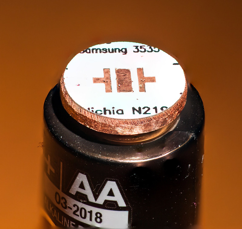
That was the hard part. I used a 1/2” 6061 bar to mount in my cordless drill. JB Welded the star to the bar. Very quickly, (the JBWeld sets up in 5 minutes) I made adjustments to the centering by laying the drill on it’s side and holding a pencil to make a circle on the turning star. If the circle showed the pad centered, I was good. Took 3 attempts to get it just right before the JB Weld set up.
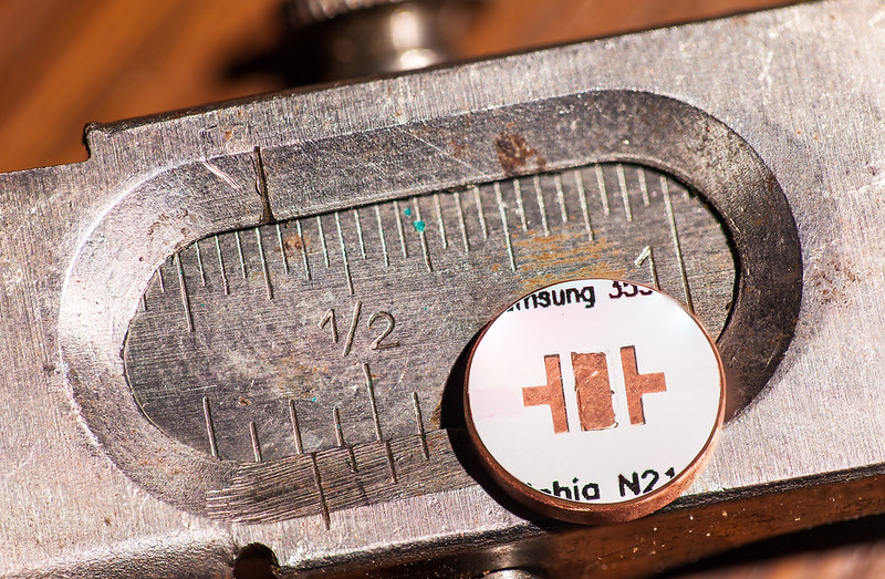
Then I used a cutoff wheel on my dremel tool to make the initial cut for size, filed it to get it where you see it now. Then found out that 11mm wouldn’t fit in my Light Engine. So filed it more to get it exactly 10mm and polished the edge smooth with sandpaper, finishing with 600 grit. Used the 600 grit to cut a bevel to ensure the traces were away from the copper Light Engine.
The calipers in this picture belonged to a late Uncle who passed away back in the late 30’s. They’re something like 100 years old. I’ll get a couple of holes drilled through this one for the wires tomorrow and then I’ll get your XM-L pad turned to 16mm. That one will be a piece o cake compared to this one…or so I hope! Tested it out with the DMM and all systems are go.
I thought that WAS a crude method! lol New to this stuff, never done that before. My next goal is to reflow an emitter, probably won’t try that one first as too much works gone into it to do experiments on.
Definitely better than what I would have come up with.
In terms of reflowing, people say using soldering paste makes it very easy. My first package to come in today was actually some kester ep256 63/37 paste. I’m going to take a picture of all the components I ordered in the coming week (once they get here) for my builds. Then in 2 months, I’ll make a new thread once I start the actual build.
Also a question for those who have reflowed. What would be the best method to reflow an emitter to a copper heatsink (for example, if I were to reflow it straight to a copper pill, no star)? Would a torch be the way to go?
definitely go with the paste, makes life so much easier and you’re less likely to stuff up the emitter in the process.
As for soldering direct to a pill, I’ve never done that, but I imagine it’s simply a case of getting enough heat into the pill. You could try it on a stove top, but I don’t know if you can heat it high enough that way, if not then a torch would do fine. I remember PilotPTK talking about using flux to prevent solder spreading, but that might be just on boards with a solder mask. Either way, i think your hardest job would be making sure the LED stays centred as you won’t have a lot of time to get it right. If you have some high melting point plastic you can use, I’d make a mask to hold the LED in place while you reflow it. Oh, and heat the pill as far away from the LED as possible, but you’ve probably already figured that out
As I’m in a similar boat with Skyrider at the moment, can someone give me some indications about solder paste…the more I learn through reasearch the less I’m sure of. It’s “dated” so your source is important to get fresh paste, and it needs to be kept cool which is going to rule out a whole lot of suppliers. And then comes the hard to know parts….like just how much to put on that tiny contact surface when reflowing an XP-G2 emitter or Nichia 219. I can see that you wouldn’t want to coat the entire visible pad, but just how much does the stuff spread out? Would a good rule of thumb be to approximate 1/4th the surface area? Looks like it’s far easier to get too much than too little, is that a fair statement?
I don’t live in a large city, so sources are going to be on the slim side. I actually saw a listing online that LOWE’s carries solder paste! Get out! Like, how fresh could that possibly be, knowing full well that most builders don’t ever reflow anything with solder paste, right? So would the local electronics store that’s been in business forever be a more likely place or would Radio Shack?
Thanks guys for all the help, there’s nuances to these kinds of things that you just can’t learn through reading source material!
DBCstm, to be honest, for the relatively crude reflow work we’re doing, I shouldn’t worry too much about the age or storage conditions of solder paste. It’s basically solder particles suspended in solder flux, so you can even make some yourself (there’s an instructible on it somewhere) with a lump of solder and the wife’s nutmeg grater. I’ve even read of people resuscitating old paste by mixing in some more flux. You can order it pretty cheap from DX at least or off eBay.
As for how much, just use a toothpick to put a very thin layer on each pad. It’s sort of hard to spread evenly so as long as you’ve covered most of the pad but can still see the pad through the solder, you’ll be fine. The huge plus of using solder paste is that when it melts it sucks the LED down onto the pads and squeezes the excess out of the side, so it’s hard to use too much (unlike with solder, where it’s very easy to use too much).
Thanks Matt, I’d read about it sucking the emitter into place and it occurred to me that while the positive and negative pads have outlets where the trace continues, the central thermal pad does not. So I am concerned with having more on that pad that might hold the emitter up and get uneven results. But from what you’ve just told me, the outflow from the two outer pads will equalize to the point that my concern is a moot point.
Thanks for that explanation. Now I just have to give it a go!
no worries Any excess on the centre pad will just get squeezed out either end of the pad. In fact, as it doesn’t have anything to sit on (compared to the +ve and -ve pads) it’s actually easier to get rid of it afterwards, you just have to ping it off with an exacto knife or a pair of tweezers.
give it a go. It’s surprisingly easy and straight forward for something so terrifying
Yeah, I know, still need the wire holes but that’s gonna get into the text so I wanted you to see it this way first. I botched it bigtime! It’s off top-to-bottom by almost a mm! But, it’s also almost a mm shorter at 15.5 so you can fudge it over if you have to. If this is horrible, chalk it up to a learning experience and I’ll think of something else to do with it.
Sorry the pic is off a bit, didn’t set up the tripod and macro rail or the lights either for that matter. Stuck the macro lens on the 1DsII and shot it on top of the rubber tail clicky boot on a gold Solarforce L2P. Not bad for handheld in mediocre light though, gotta love Hybrid Image Stabilization!!
So whatdya think? Go ahead and cut the holes in between the pad and “XML” on top for “+” and under the “u” at bottom for “-”?? The way this board is designed, I don’t see that you’ll be able to use the reflector locator/insulator, double pads kind of mess that up it would appear.
Still looks pretty good. I’m wondering if I take a dremel to the pads and remove them then expose the trace under the white layer, maybe that could work?
How about a notch where the top right - sign is and another notch on the bottom left + sign. I think I can then solder to the trace that is not exposed in the pic and still be able to get one of those positioning gaskets on there.
Want me to cut the pad out with the notch? I can probably go ahead and clear the trace while I’m there, I have a very very small bit for my dremel that should work well to clear the mask.