I wonder how it would compare to the jeweler’s rouge I use (for more than just jewelry, but on cloth wheels on the Dremel)? It comes in several “grits” (not gritty!!) denoted by color.
Even the finest jeweler’s rouge won’t get an optical-grade mirror finish.
At least not in my hands!
All the reflectors I’ve bought seem to have a wet looking finish, even the OP ones. It’s tough to get there with just polish. OTOH, maybe a fine “scratch” would just be like “Ultra OP”…
I’ll go back to lurking, since I really do want to see this!!
Pretty sure at WalMart, or Advance Auto or something. Mine is pretty old. lol
Felt wheels for dremel leave scratches. I use the paper backside of 1000 grit wet/dry sandpaper for the polish. Yep, flip the sandpaper over and use the paper backing! It’s harder than the cloth and doesn’t leave the scratches that even an old 100% cotton T shirt will leave. Another gunsmithing trick.
Edit: Mine’s actually old enough that it says Mother’s Incredible Billet Metal Polish on the can. Oops! Never mind! That’s still what it says! lol
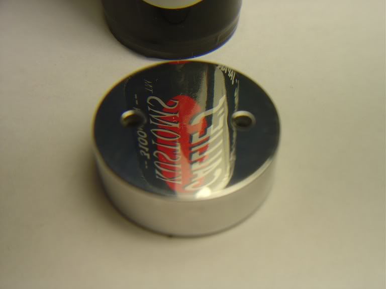
This is a 1 AA mini mag pill I used the Mag & Aluminum Polish on, that’s all I used. Well besides the 1000 grit sand paper that I used right before the Mothers.
.
.
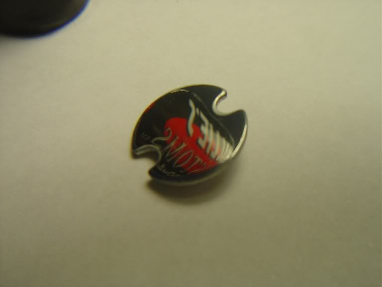
The led Board lapped.
.
.
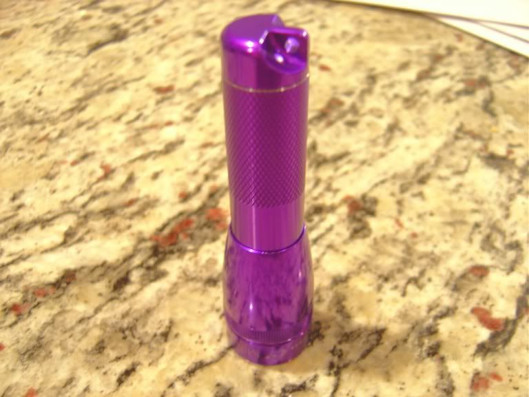
And here’s what it went into.
.
Spoken like someone with access to machine tools!!
It’s really as simple as it looks, IFF you can cut tool steel to a continuous curved shape, then flute it, cut chip-clearing gullets, and harden it… (I wondered why the OP blue Tempered & didn’t stop at quench Hardening. Then I realized you’re just using it to cut Aluminum, so it probably doesn’t matter.)
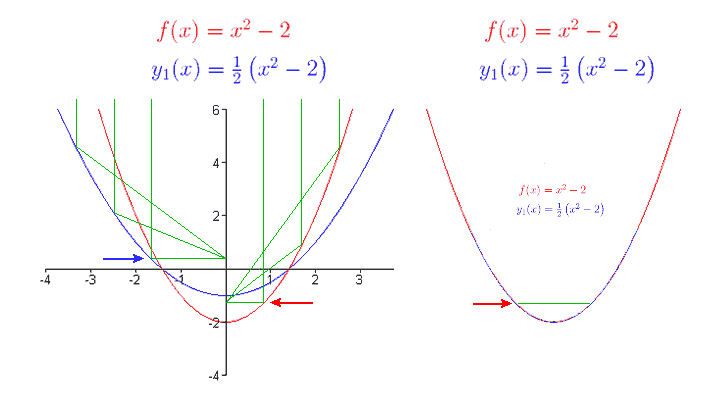
If your lathe is CNC, your troubles are over! Just chuck up a piece of round stock the size of your lens opening & upload a Parabola. Suppose it’s the Blue one in the picture above… I believe it’s described by the formula in blue. Whatever program you’re using to support your CNC probably has a “Draw me a Parabola” macro already built in…
OTOH, if you can cut a parabola in tool steel without CNC…
Nah. You don’t need them. Think John Henry vs. the Steam Hammer…
If you can turn complex curves reliably, you’re worth more than any CNC setup anyway!
Maybe you could “freehand” one that would “fix” the color rings… Jeez, I hate how pathetic that sounds, but the funky-color XM-L rings really piss me off. Sorry.
I’m getting in the way of this thread. Back to lurking…
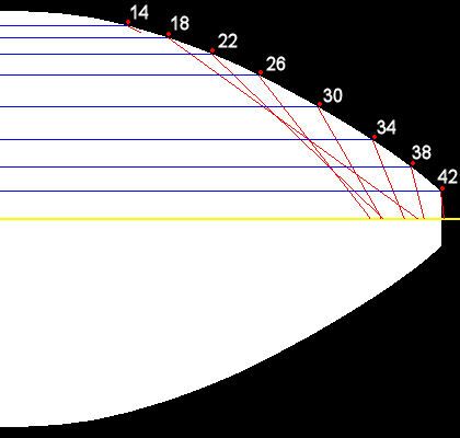
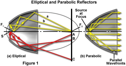
Bucket, there’s a problem with the shape of your reflector. Using the contour in your picture, I plotted 8 angles in increments of 4 degrees. I tried to err in favor of it being right but they’re still way off.
All the angles should intersect at a point on the centerline where the emitter will sit.
I don't think you accounted for the picture being taken at an angle. I'm not saying it's perfect because it isn't. It's an approximation. I advanced .025" at a time and took a cut to diameter then filed and sanded and polished. It's not too far off though.
Judging by the machining marks, it’s showing the mid section pretty accurately. If the angles I made were a little off, I’d chalk it up to the picture’s angle but they’re way off. You’re putting a lot of work into this. You should shoot for perfection. For every degree off at the reflector, it’s 2 degrees for the beam.
You can’t just cut the bottom where you want. You can only cut the top. The reflector’s angles and emitter have fixed positions regardless of size. To focus on infinity, the light from the sides of the emitter must hit the reflector at a it’s 45 degree angle so this is where the emitter should always be.
The blue one is just part of the red one scaled up. Is it considered a fractal?
Thanks for the pic!
If the focal point is inside the reflector, I might just have to get fancy and put the emitter on a pedestal, raise it up to where it needs to be. Then the reflector itself can sit on the copper pad, with the emitter up inside where it will be focused. A bit of a pain, but doable.
That will optically be no different from just sanding the reflector down up to the focal point, no pedestal needed, any reflector part under the led isn't used anyway because a led does not emit beyond 180 degrees.
With the exception that sanding the reflector down to the focal point will widen the base and have it sitting on the electrical contacts. There are ways to go about it of course, but as we can see, the parabolic equation for these LED’s is a true PITA.
Would we gain anything by looking at it from a de-domed perspective? This will (or will not?) broaden the angle of emission to further utilize the walls of the reflector. Many many arguments on this.
When I set out to make my own reflector, I was going for something about like what Bucket has done here. I just lost sight of the goal while focusing on the means and failed. But this design is to my liking, which is why I’m so interested.
Edit: Lightme, what if you reverse engineered the angles, as a copy of what our light will do…instead of bringing light rays in from the mouth and finding the focal point, take the light rays out from a 125º emitter and see where the light goes? This accounts for our spill/hot spot areas, does it not? There’s no way to capture all the rays of emission from the emitter as some will leave the reflector without ever touching it, in a direct path. I’d like to see what the computer generated effect directly from the emitter produces with this design of Buckets. Guess I will, first hand, when I get it in the light.
A parabola is the only thing that works because the entire surface will always focus on infinity no matter how big or long you make it. Every point on the reflector has the correct angle of incidence to reflect the exact center of the light source forward. Why would you want the reflector focus light from anywhere but the LED’s center regardless of how big and fuzzy the source might be? It doesn’t matter if you have a 125º emitter, the best you can do is focus on dead center.
If you measure the angle of incidence where the light hits the reflector and the angle that it leaves the refector, you’d see they’re the same whether you look down the barrel or from the center of the LED. The optimum reflector shape and LED postion (for throw) is universal. If you’re saying a parabola sucks because you can’t physically adapt one that wasn’t made for an LED, then never mind.
I’m not saying that, what I am saying is the very idea of focusing to infinity is a dream. With light requirements quadrupling for every doubling of distance there is just no way to throw to infinity. It’s going to break down. So if the ideal parabola has light leaving the flashlight in a parallel beam from a 1 1/2” diameter aperture, it’s going to take far more power than we can supply with a single or double cell configuration to throw “forever”.
I know a lot of people are in the elusive chase for the furthest thrower. But can you see a 3’ circle at half a mile? I sure can’t! So it has to be relevant. If the beam is spreading as it goes out, that’s fine with me, as long as it’s illuminating a fair amount at 100 yds or so, even out to 200 yds, it’s doing the job I want it to do. Over that is pretty ridiculous. I have an HD2010 that hits over a thousand yards. Have to take a zoom picture then look at it full size on my 24” Professional monitor to tell, but it does it. Even at 600 yds, I can’t make out with my eyes what it’s doing. So 200 yds is plenty.
When I speak my opinion, it should be clearly obvious that it’s just that…my opinion. I can’t make blanket statements as to what works for everybody in the whole world, nobody can as far as I know. So it becomes relevant to the perspective of the user. As usual.
Then again, parabola’s were originally designed to receive light and sound, not transmit.
The reason a paraboloid is difficult to optimize for an LED is simply because it was never meant to be used as such. The design is merely an algebraic equation of a slice through a cone. It’s been found to focus light and has been used as such since the 17th century, but the LED has different requirements, hence the issues.
If you want the best etendue, you have to focus on infinity. That gives the best throw with the least change in spot size between distances. If you want a wider beam or a hotspot that blends seamlessly to spill, it wouldn’t take much of change from a perfect parabola but throw is going to suffer, especially if you change the angles at the wide end. Do it wrong and the hotspot might look good at one distance and form a circular pattern at another.
Before I started playing with good LED flashlights, I thought I wanted the best thrower, most lumens, direct drive, etc. I found the perfect light for me is a cheap C12 with an XML2 T4 (high CRI on copper), OP reflector and a 3A driver. Far from the what I thought I wanted!
