I found out that Tesla handed out 18650 cells to educational institutes, and out Roboclub has about 210 of them in 7 boxes of 30 cells.
I asked the officers if I could use them and I got a short but satisfying reply:
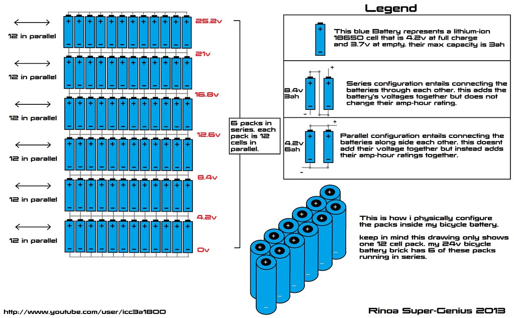
My plan is something like this, but with 16 cells in parallel instead of 12:
I did manage to recover the SLA batteries but they held only 4,000mAh instead of the original 10Ah and their internal resistances were pretty high. I’ll have to recycle it.
Nice! That should be a great upgrade from those SLA batteries!
For what it’s worth, if you’re doing a complete overhaul of the drive train and battery pack, you might want to consider a different platform which has a decent suspension setup. I remember when I used to live in the Unites States I could pick up an old moped for under $50 with a busted motor, but otherwise working suspension. A decent MTB with a hubmotor might be an even lighter and nimbler option (though obviously it would be pricier).
Thanks for the tip, I didn’t realize how much progress I would be making with the scooter. It first started out thinking that it would have a bad fuse and some dead SLA batteries, but I now think having decent suspension would be nice too, haha.
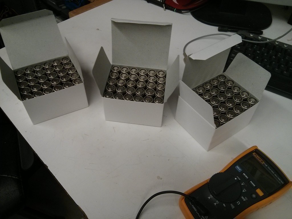
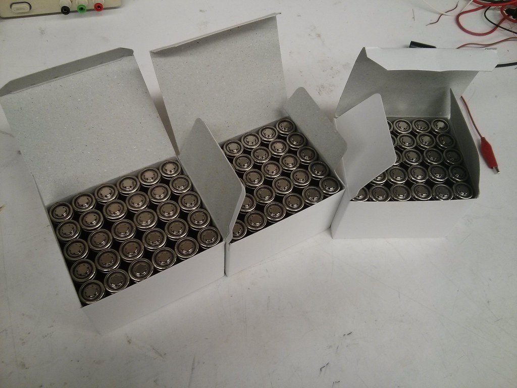
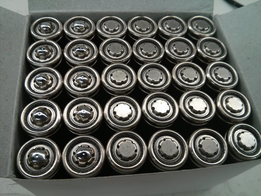
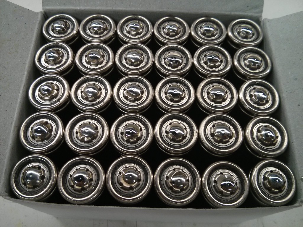
Tonight I visited Roboclub and got the batteries:
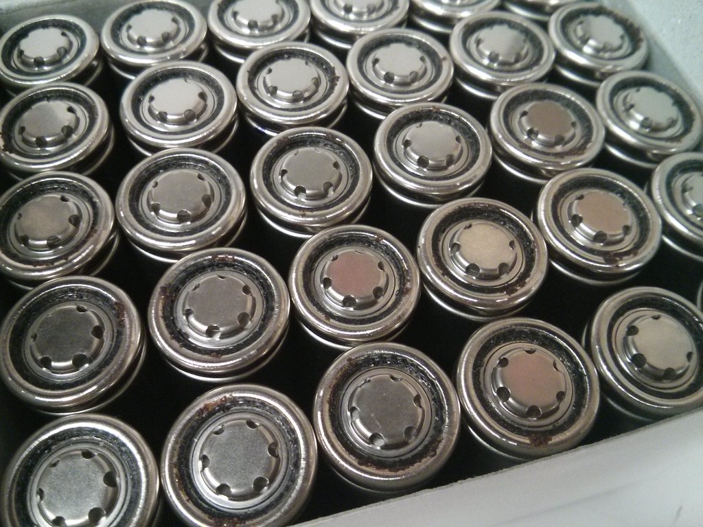
The first thing I did was to visually sort through the ones that had corroded or rusted. There were surprisingly a lot of corroded cells, about 30% of them. I grouped them into a box:
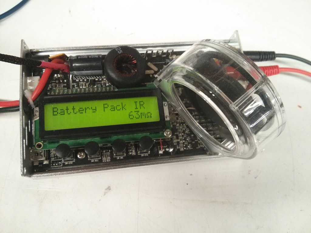
Next, I measured all the cells’ internal resistances with my iCharger. It was surprising that over 60% of the non-rusted cells had exactly 63mOhms of resistance. About 20% had 71mOhms of resistance and the remaining 20% were spread out between 64 to 73mOhms.
surprised about the corrosion. Sounds like storage at high humidity possibly combined with some contamination on the cells. Glad I am in Reno, NV where the humidity is low enough so corrosion is a minimal problem.
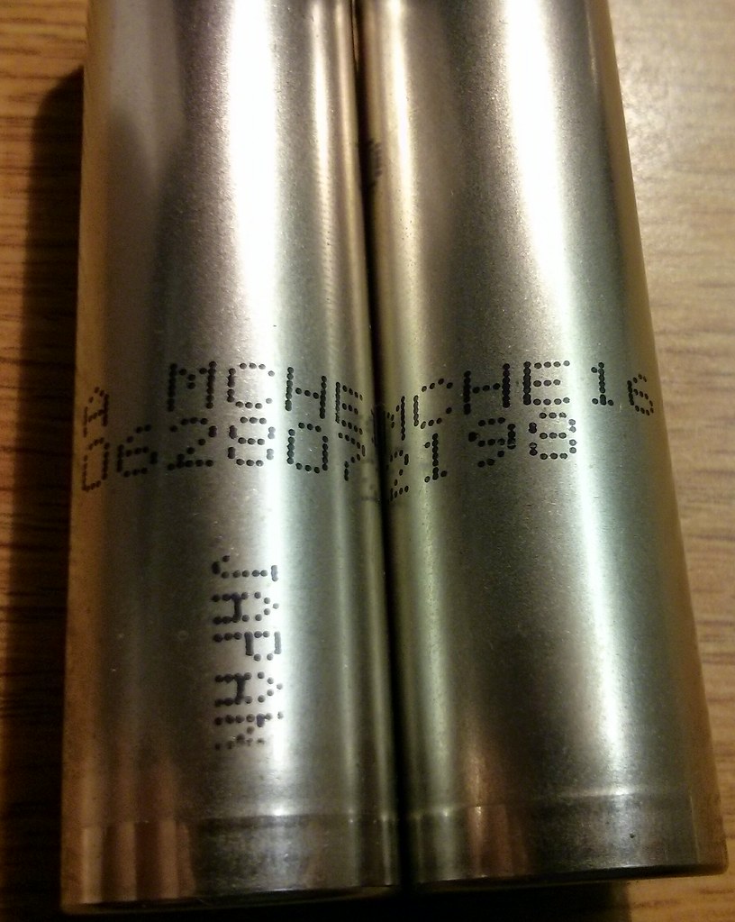
Yup, they are labeled: A MCHE16 and a serial number. Seems like a Panasonic cell, can anyone confirm?
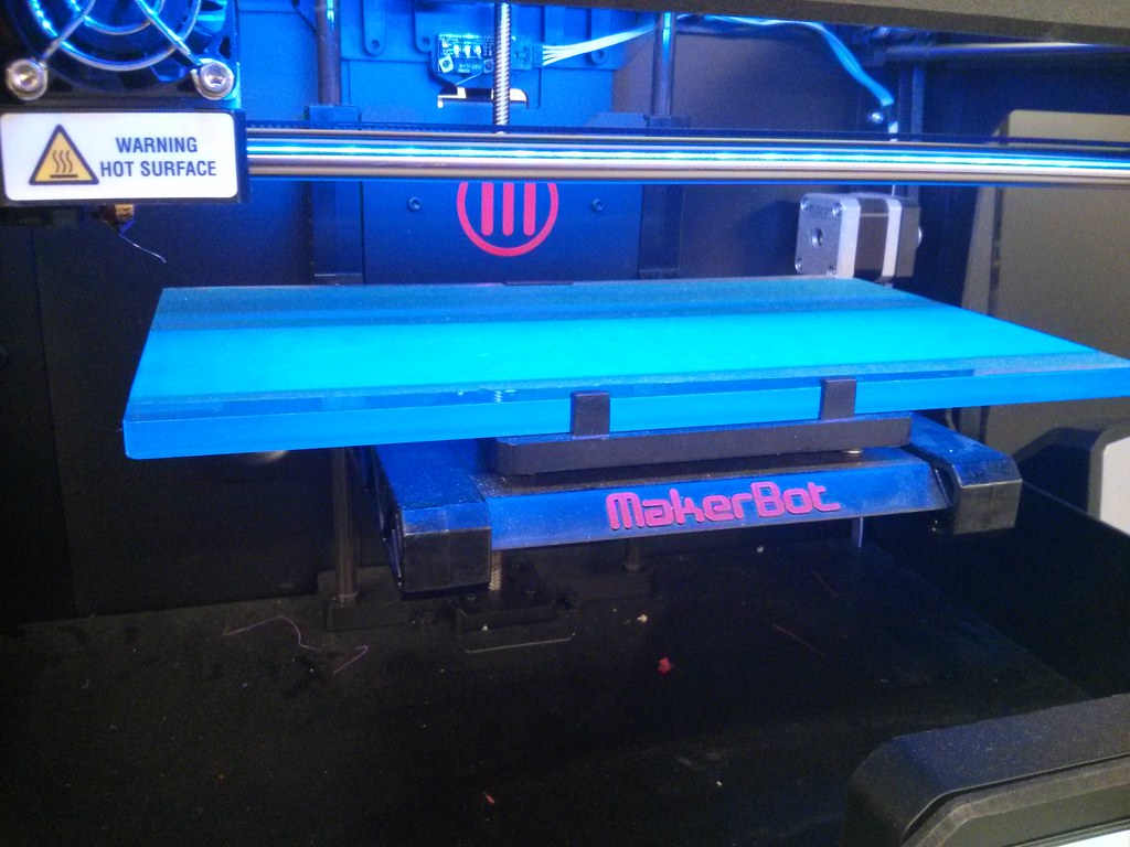
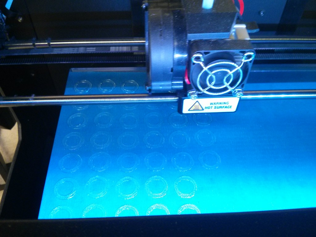
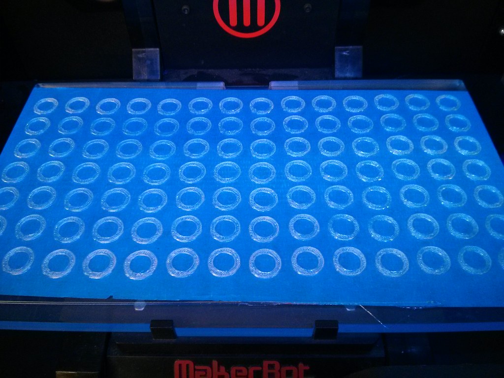
My next step was to make battery spacers. These were not shrink-wrapped, so I had to isolate the cathode from the circumstance of the top of the cell, which was also part of the anode. 100 spacers? No problem. I just 3D printed them:
Here’s a clip of making a sample spacer:
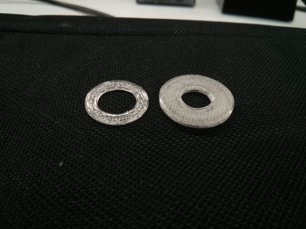
Here’s the comparison between the a proper one and a one that I made too thick and got confused between metric and imperial units:
Yeah, I was pretty surprised about the corrosion too. It was interesting how only top of the cells had been corroded, between where the anode and the cathode are.
While the 3D printer was spewing out spools of translucent PLA into spacers, I went on to solder some tabs on the cathode:
I’ll be testing out the capacity of four randomly sampled cells in parallel to get a ballpark of how well these perform.
These were sent from Tesla directly to our Roboclub, so that’s something you don’t see quite often. I took a photo of the package but it was slightly too blurry so I’ll get a better shot next time. Nah, here it is:
Don’t use PLA! It softens at temperatures you are likely to see in operation. I’ve seen PLA stuff left in cars melt.
And DON’T solder to the cells. Hunt down a proper tab welder. Do a quick test. Solder to a cell and immediately touch it with a wet paper towel. You hear that sizzle? The same thing is going on with the electrolyte in the cell… and it breaks down at lower temps than spit sizzles.
Thanks for your warnings. Unfortunately I don’t think I have any choice in the 3D printing material or the usage of a spot welder. The spacers aren’t the only things separating the cathode from the anode; I am using 14ga with insulation to connect the cathodes together. Even if the spacers do fail, I don’t think it would result in immediate failure. I also do recognize that I am shortening the battery life by soldering on to the cells, but it’s only for a few seconds. I’d like to get this setup up and running as fast as I can, so I don’t think I have enough time to build a spot welder.
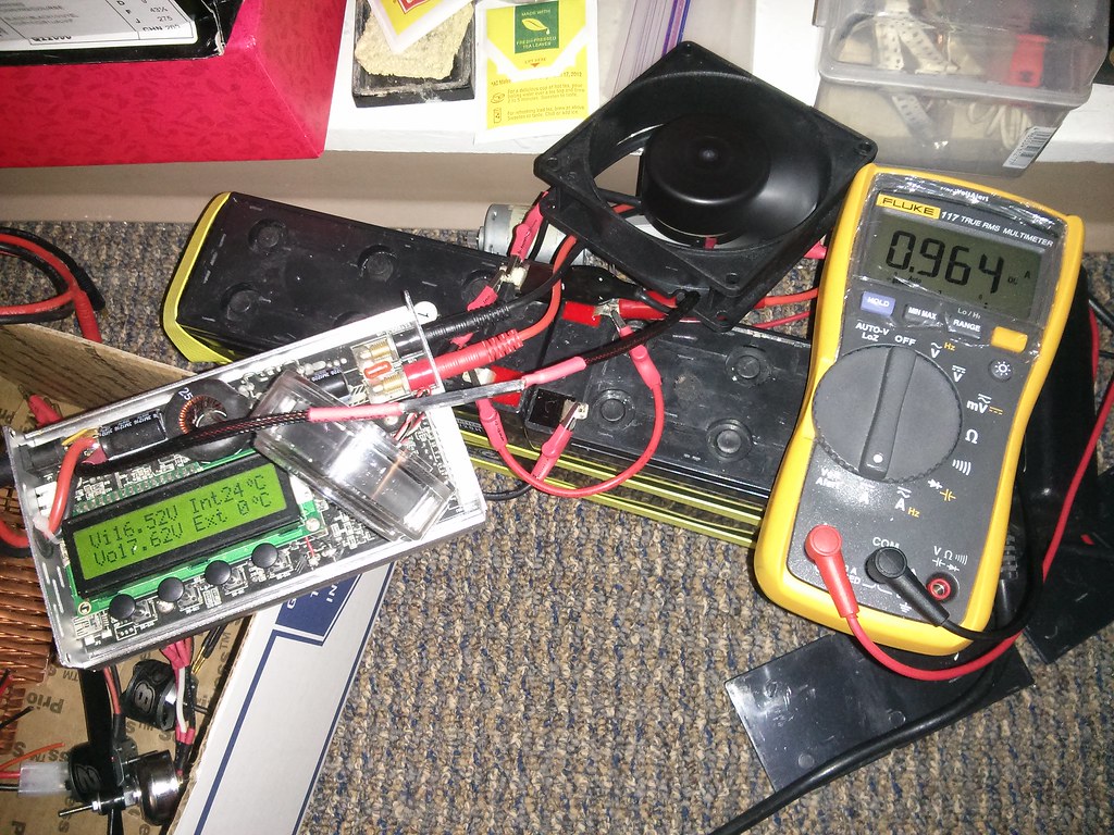
Wow, you have a good eye. How did you know it was an Asus fan? I think it’s meant for a laptop though, as the air intake and exhaust are perpendicular.
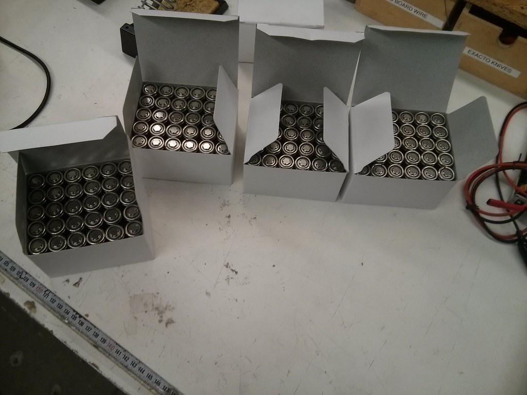
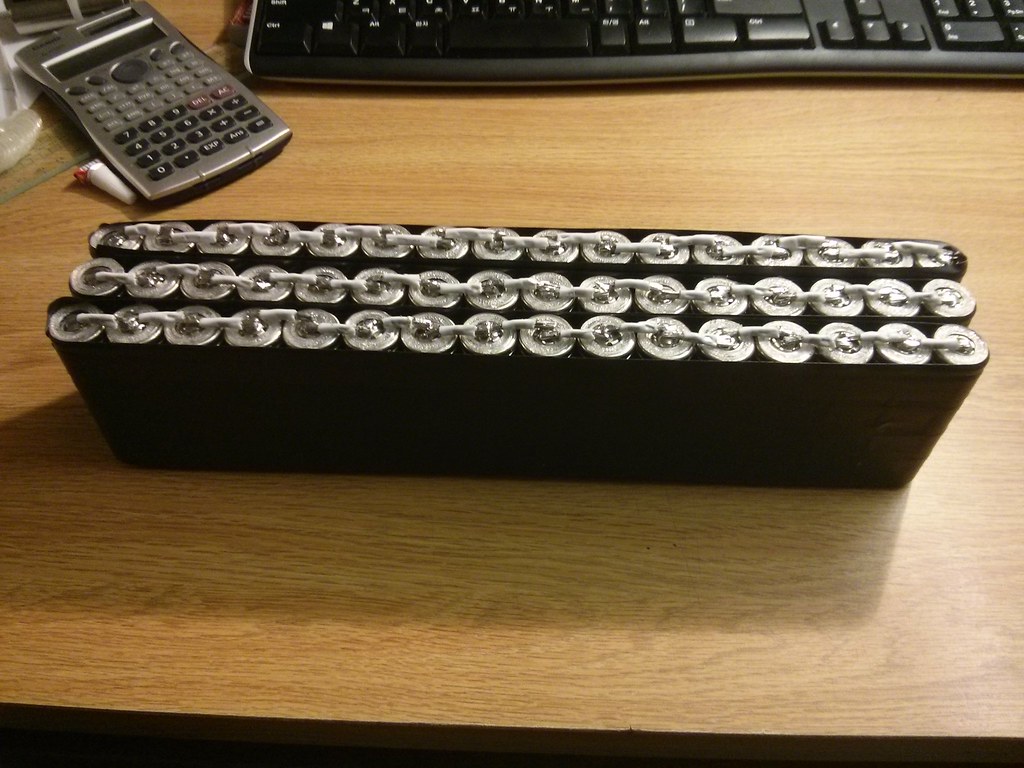
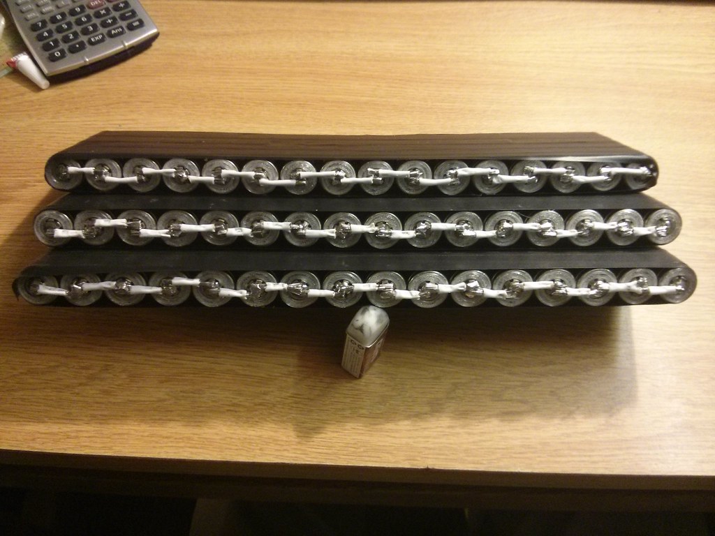
I spend the Sunday afternoon soldering the cells together. I’m about halfway finished; I have three more packs to build:
I got quite tired after five straight hours of soldiering, wire stripping, and taping.
Nice work! There are easier ways to do that, you know
Are these true Li-Ions at 4.2V charge?
My scooter is taking shape. Got 3 new cells in the mail yesterday. This thing is going to be better then new when I’m done with it.
A lot of dirt and grease scrubbing going on!
Yeah, I’d get a li-ion or LiFePO4 pack if these cells weren’t free.
I think it’s also a fun and rewarding experience.
Good luck with replacing the cells! Do you plan to charge them in parallel or in series?
Yup, 6S16P. I was planning to go 7S for more punch but realized that my charger would only charge up to 6P. Refrigerating cells is a good tip, thanks. I’ll try that out after tomorrow’s exam.
I’m going to attach balancing leads to each of the 6S packs. I’ll be using a hobby charger to balance charge them with balancing connectors and I won’t be using an internal cell management PCB.
Back in 2008 I won an ASUS Maximus II Formula at a LAN party, and it came with a couple of those fans which could be strapped to the CPU voltage regulator ’sinks to provide additional cooling. I’m not sure why I still remember that silly tidbit of information, but I instantly recognized it when I saw your charger 0:)
Will your hobby charger be able to charge up the pack at an adequate speed?
Wow, congrats!
The charger is rated for 250W, so in theory it should be able to charge a depleted pack in 3-4 hours, which I don’t think is too bad. I probably won’t charge that fast for the longevity of the cells though.
When running the pack you should at least use one of those RC battery monitors on the balance leads so you will know if a cell group begins to droop before the others. Many have an audible alarm (which can be connected to a louder circuit if needed).