Not usually. However, if any pins are grounded except for GND, it can interfere with flashing. Most common drivers can be reflashed as long as they don’t have any stars soldered. One exception is the first batch of Convoy’s new red drivers, which have pin 5 grounded and need a trace cut. This should be fixed in the second batch though. Anyway, it depends a lot on which type of driver you’re using.
The same issue about pin 5 being grounded also applies to the original FX-12 driver that can sometimes be found in stock Convoys.
Have anybody succeeded in working with USBasp like 
under win_10 x64?
Have tried with many drivers with no success.
The only way I managed to get it working is to run VirtualBox with WIN_XP as a guest OS under my WIN_10.
Linux requires “sudo” when flashing, I wonder if Windows requires admin rights?
Also, in my experience, the style of USBasp can make a difference in flashing success. It’s not the same one, but see my post here (and the ones before it to see the symptoms I was running into).
I have no probs on Win 10 x64 - two different computers - high end gaming desktop and a laptop. No issues, works great w/Atmel VS 7.0 Dnld'ed driver from here: https://protostack.com.au/. Believe certified for Win 10. On this page: https://protostack.com.au/shop/accessories/usbasp-avr-programmer/
Oops - just noticed your picture of the USBASP - it's an odd one for sure. Only one I ever used looks exactly like the one on ProtoStack, also available cheap at other places like FastTech. It must be labeled V2.0
Tom E, had already bought 2 like on my prev post. Will keep it for now as far as it works at least under VM.
Look like I have to dig USBasp - USB programmer for Atmel AVR controllers - fischl.de for an appropriate driver.
I bought one from FastTech, just like the link in the OP.
I believe my cable went right just like the OP.
I’m little bit curious so I just test one pin on the pcb against all each pin out the connector.
I’m newbie in the electro stuff, I just know the very basic. I put the analog multimeter, and connect them on by one.
Interesting thing is, several PIN seems “connected” with each other PIN since the needle moves, some almost half, some just small.
Is this normal or I got defected item? Especially at the odd PIN number, they were in contact.
If MCU pin 5, 6, 7, or 8 is grounded, flashing won’t work. Pin 4 should be grounded, though, and pin 1 is usually floating. Pins 2 and 3 aren’t connected.
Please be ware that I’m not techie guy. So I don’t know 100% what I am doing…
I test PIN on the USB pcb with the 10 PIN in the connector, here my result:
PIN 1: with PIN 2, the needle move almost 3/4 radius, others no movement.
PIN 2: with PIN 3, no movement, against the others (1,4,5,6,7,8,9,10) very small movement
PIN 5: with 1,3,7,9, no movement. with PIN 2 needle move 3/4 radius, with PIN 4,6,8,10 small movement
PIN 6: with 2, needle move 1/3 radius. with others (1,3,4,5,7,9,10) very small movement
PIN 7: with 1,3,5,9, no movement. with PIN 2 needle move 3/4 radius, with PIN 4,6,8,10 small movement
PIN 8: with 1,5,7,9,2,4,6, 3/4 radius movement. with PIN 3 no contact. with PIN 8 and 10, in contact.
I got bad item? Time to buy another new one?
I don’t think I understand. Doesn’t sound like we’re talking about the same thing. Or maybe I’m just too sleepy to get it. Does it make sense to anyone else?
It could be a translation issue.
I understand. Let me re-wording my chit chat with picture.
Some time, picture say more words…
The left pic, I say the “connector” and the right pic is “pcb”. Easy term for me to understand the situation.
Just because mine doesn’t work like it should, I simply test each PIN on the PCB against the CONNECTOR.
The other part, which is the cables and the SOIC8 is well connected, each of them doesn’t connected except their own PIN number.
So I assume the problem must be on the pcb/connector. Either it’s bad solder or something broken within the pcb layout, technically.

The result on the PIN is my above post. Hope this help to understand what I mean and talk about. ![]()
Or there could be a grounded pin on the driver itself, like the first batch of Convoy’s new red driver. It can sometimes be necessary to cut a trace to enable flashing.
My sample still use the old green pcb.
Both driver seems okay, no grounded pin.
I’ll to buy several pieces again and make another try.
Yes, but what green driver is it? 105C, FX-12, or something else? Could you share a photo of yours or a link to what you’re buying?
The drivers taken from S2+, I change with A6 and like to play around and learn how to flashing new / different firmware with it.

One of them is like the pic.
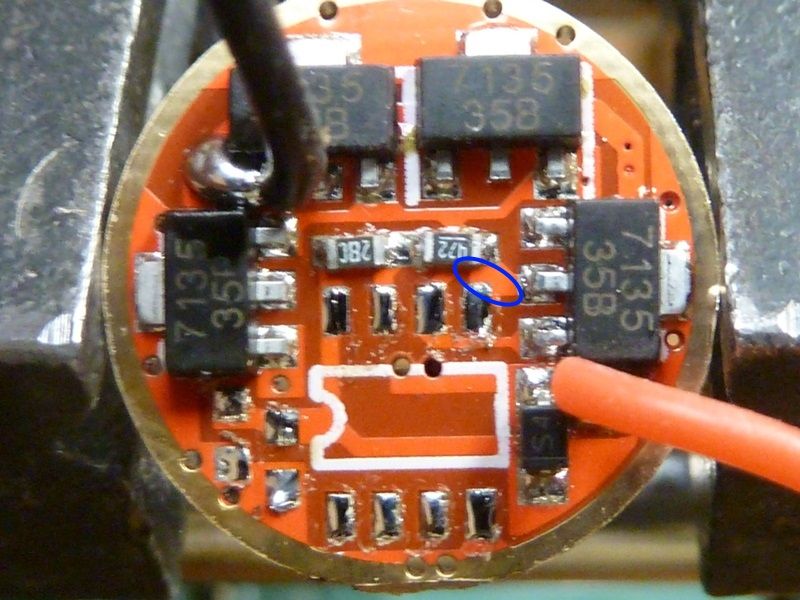
TWN, that appears to be the FX-12 I’ve been asking about. If you flip it over, you’ll likely see “FX-12” in white print on the board. And if you look closely at your driver, you’ll notice the same grounding issue that TK pointed out. These are pretty much the same driver, just a different color.
Either swap out for a different driver (like the nanjg105c) or try cutting that trace to isolate pin5 of the MCU. I recently did the same exact thing with a driver from the S2+, cut the trace. But I found out that some of the components (the capacitor?) must be slightly different. The method being used to track fast presses (for advancing modes) kicked in around 1 second instead of 1/2 second. Anything shorter than that didn’t even register as a press. It was pretty strange. If you have easy access to drivers, I’d recommend ordering some of the 105c drivers. Fasttech has them at a good price, see here.
You can see the trace that is grounding pin5 of your mcu. You can try cutting around pin5 - make sure to cut all the way through the trace. Even if you end up ordering a 105c, this will allow you to test your clip in the meantime.
On mine, I managed to either cut the voltage divider’s trace or cook the resistor; not sure which. So, mine now has no LVP or battcheck and it takes forever for the SRAM to decay since it has no path to bleed off its charge. Oops. At least I finally got it to flash though. ![]()
The nanjg/qlite drivers are much easier to deal with.
Thanks for the link, gchart. Appreciate. I already made couple of new USBASP yesterday, well, just in case.
About the drivers, I’ll consider it. For now, I just take some pictures, at least the 2 drivers I’ve taken out from the original flashlight to play.
Here the pictures, one show FX-12, the other just Convoy in the back of the driver.


And the zooming out of the MCU PIN as below:


However, to be frankly I don’t know what is the grounded trace between the mcu pin 5 and the other stuff. Is that the “darker green” on the pcb ?
Because what I thought so far about the ‘trace’ is only some soldering which connected between some part, not the ‘trace’ under layer pcb.

Thanks for all the help and information.
The trace is like a thin copper wire, most of which is covered up by “solder mask” to prevent accidental contact. It shows up as the lighter area.
I’m on my phone, but let me see if I can find something to sketch on your image with in a sec.