I would be connecting the output from the LED driver to LED + and LED- on my strips then?
This one looks like it may work, it is only 300mA though but if it works you can measure Vf and confirm it.
The 18-25W one with 54V-87V
Yes, that’s what I think. + from driver to LED+ and - to LED-
These are SMD 5050 LEDs but there are no resistors on the board. That is the way you match the 3.7V (max) for the LED to the input voltage. They are either individually powered or more likely as a group in series.
You can see the voltage matching resistor on these strips. One resistor for each 3 LEDs.
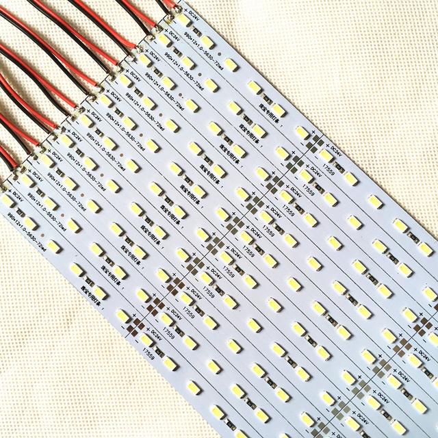 Picture is SMD 5630 LED strip.
If you use a variable DC source, start out low and work your way up until they light.
I was just looking at that one! Will do some testing later this week and will report back
You are a star arek98!
Vegas, these are strips made to be easily powered by 24V constant voltage power supply. This one has 6 LEDs (other meant for 12V will have 3 in each segment), their Vf is lower than 24V so as you noted there is an resistor to limit current end drop excess voltage.
What is inside of Philips tube looks like LED boards just with LEDs, there are no visible resistors or other components. No need for them since they are driven by custom driver that comes in lamp.
We are trying to figure out without schematics of connections how they are connected.
So far best guess is that there are 3 separate boards each with 54 LEDs connected in 3 parallel strings, 18 LEDs each string.
I will get chance to test them out tomorrow and will post back with results.
Thx Davevo, hope I helped ![]()
I thought this one you can get fast since it is in UK and is not expensive.
You can get one, try it and if it works and is bright enough order more or at least measure Vf (assuming you have multimeter that is)
You helped me out a lot. I have good test equipment yes, and it’s good that I know enough to be able to take on board your replies and understand.
I knew I needed a driver to drive them direct, but wasn’t sure whether they were series or parallel. So I couldn’t really work out what power output I needed to look for.
What I would’ve prob done is sacrificed one tube strip by testing it’s limit but I don’t like killing leds if I can help it. That’s why I asked here first.
Thanks again sir!
I have ordered 2 of those drivers.
I have nothing to lose because the tubes I have are free.
Ok
I have tried each led with 65ma and 3.3v works perfect I can see there is 6x strings of 9 chips in series if that makes sense?
I selected 60v and 300ma set constant current on power supply. I can connect the + and - from power supply to the brown and blue wires on the tiny plug socket.
Nothing happens. If I do the same with probes further up the strip where the first section joins at No 54 led where the solder blobs are on the + and - it will light up the last 2 sections.
If I do the same on the last section it only lights the last section.
Dave
Right all sorted.
I used a 600w dc-dc boost converter which does up to 95v. Set it up on a 100w cob led and set current at 400ma and 40v.
Turned down the current pot a few turns some more. Hooked it all up and increased the voltage to 78 and 300ma. All works perfect. Wasn’t enough obviously in my bench supply.
I will run them at that with the drivers I ordered. Very happy
Thanks everyone.
Dave
Hmm, so it looks like 3 parts are in series not in parallel as I thought.
If that is true and what you see is true (6 strings with 9 LED on each part) it would mean that you have in total 6 strings with 27 LED each.
That would mean that you need about 90V to light them all up.
That would explain why 60V is only able to light 2 or 1 part.
Ops, I saw your last post after I wrote my reply.
Glad you figured it out!
Thanks
Nothing damaged have checked all 5 strips and they all light up. Those 2 drivers will be here tomorrow and they should work a treat
Just got these drivers today and have checked the output voltage and it’s 109v DC. Is that because there is no load on it?
The 18-25W one with 54V-87V
Thanks
Dave
A constant current driver works by tuning the output voltage at the right value for the preset current to flow, generally using an internal sensing resistor/shunt to do this. Having no load means the output impedance/resistance is super high (open circuit) and no measurable current flows out, this is sensed by the driver which jacks up output voltage to maximum in its aim to make current flow.
Cheers ^:)
Awesome explanation
Thanks
A big thank you again to everyone on here who helped me! Now I know a little more about drivers.
Everything works perfect.
Dave
You're welcome Davevo 5k.
Just had a brief reading at the previous posts, this looks like the case of unnecessarily complicated retrofit products made and sold by people who do not have a clue. Of course bad. I also had tubes in my kitchen nearly 3 years ago, but opted for a led boards and drivers DIY conversion which ended up being very satisfactory. If something gets in the middle (ballasts, starters, etc), better remove it. Understanding the intricacies helps.
Cheers ^:)