Update! So i am able to compile and flash tido's files, incase it helps someone else who's just starting out i had the wrong filename in the makefile (doh!) also i had the chip as a tiny13a switching to tiny13 allowed avrdude and my cheapo ebay $6 programmer to work correctly. Nice moment when it all worked. I'm getting there but am having trouble with the #define's! I would like no memory, programmable, pin switch mode switching, but i'm not sure the mode setting when off for 1second will work with programmable modes, which set when on for a few seconds, please let me know if you've already tried and it does/doesnt work thanks. Better go now, work tomorrow,yawn. Ta
For no mode memory, uncomment the "#define NOMEMORY". Mode programming works with both switching methods. Of course, pin-state based click detection only works if you have added the external capacitor/diode/resistor circuitry.
Hello, everyone.
First of all, thanks for the excellent work you're doing here!
I'm a bit desperate. I'm new to all this stuff (although I've already built many bike lights it never involved programming). I was able to understand most of critical parts of the code, I succeeded in compiling it and making a 2-mode version with no memory. But now I'm really stuck (despite several tons of information I had to learn and process).
I need to switch modes with a momentary pushbutton without interrupting power to the driver. As I understand from the schematics I've seen, the button should short-circuit ground (Pin 4) and some other pin (Pin 3, for example). It seems it has something to deal with the Pin Change Interrupt PCINT0, but, alas, I'm not a coder and I've never used C++ before (only wrote some elementary BASIC stuff many years ago and have already forgotten it all...). Can you just, please, throw some code at me I could use? I'll be most grateful if you also point me on how to tell a short press from a 3sec press and hold.
Thanks in advance.
Hi everybody,
This is seemed off topic. Since I have tried Tido's wonderful program in July, three switches are worn out.

The 2 pieces on the left which I bought from DX only survive for 5 days. The right one which I bought in August finally the power on lock was worn out yesterday. Suppose I switch it 100 cycles everyday, 100 x 30 x 4 = 12,000 cycles. However, the switch is rated 200,000 cycles. Did you guys also have the same problem?
@stronge: That would require a substantial rewrite, as it has to react on an additional switch instead of being switched off. When I get my TK35 clone, I'll probably mod it to a parallel setup with an NANJG105C and then I need to do exactly that. I can post my code then.
@Microa: I doubt it's the firmware's fault... I actually never had to replace a switch yet.
@DrJones: I replaced with a new switch and the light works perfectly well. I think that it would be better to use a on/off switch to control the power, another momentary pushbutton to change mode. The Con is we have to modify the code and the driver board. The clicky switch seems to wear out quickly while changing mode in fast half press.
new here, and only half new to electronics ;) after some analog pwm issues, i think i need to step into the world of micro controllers.
what do i need to add to get a attiny13a to work for the bread board like in your picture above?
edit-- didn't read on ahead to see that this is a 9-page thread. i'll do some more reading in case it answers my questions.
To run the ATtiny:
- the solderless breadboard
- the µC
- some kind of 1.8-5.5V power source
To give it a possibility for some output:
- a LED and a resistor, like in the image
- lots of other things are available of course
To give it some input:
- a switch (like in the image)
- lots of other options (e.g. sensors) here, too
To program it:
- a programmer (like USBasp)
- some wires to connect the µC to the programmer
- Software on your PC (Compiler, IDE, programmer utility)
Just got the usb programmer module and installed AVR studio. Got the general idea. I'm stuck however in identifiying pins on the programmer, ribbon cable.
I plan on going without the SOIC clip and use clips to the appropriate legs. I cannot however figure out the pin numbering.
 which one is pin 1?
Or better with the stock ribbon cable on you get this:

From wiki. Which wire is what?
Upon idnetifiying those does the results relate to?:

That's all. :)
I'll really appreciate if someone is kind enough to solve the pin numbering mystery to me. :)
| Pin | Function | Function | Pin |
|---|---|---|---|
| 1 | MOSI | VCC | 2 |
| 3 | NC | GND | 4 |
| 5 | RST | GND | 6 |
| 7 | SCK | GND | 8 |
| 9 | MISO | GND | 10 |
So on t he 5-8 side of the clip you only use 2 wires 5 to RST and 7 to SCK on the 1-4 side use all 4 wires 1to MOSI, 2 to VSS, 3 to NC and 4 to GND............ clear as mud.
SOCKET PIN 1 MOSI --> IC PIN 5 _________ SOCKET PIN 2 VCC --> IC PIN 8
PIN 3 __I I PIN 4 GND --> IC PIN 4
PIN 5 RST --> IC PIN 1 I I
PIN 7 SCK --> IC PIN 7 I__ I
PIN 9 MISO --> IC PIN 6 I I
_________
I appreciate the effort but i'm clueless which is pin 1 on the cable. When i get that all will be simple. Thre are no markings and i would not just go and assume...
Is that correct? Should be.
Yes, the red line marks the pin 1 of the socket.
Thanks to all.
Good news I just had a chance to take apart a Shiningbeam P-Rocket with the new updated Nanjg driver and it did have a Atiny chip and I was able to reflash it with a standard program I have been using.
Any sample reprogrammed files i can have to fiddle with (still waiting for clip to attach to the tiny)? I have the avrstudio ready.
If some1 needs this is the windows driver for the isp programmer: http://www.mediafire.com/?mj9qqs83rnlk2ab
Hi all,
I have a Pololu AVR programmer that I have connected to an Attiny13A by soldering. I believe I have the pin-out correct, but when I run AVRDude, I get the following errors:
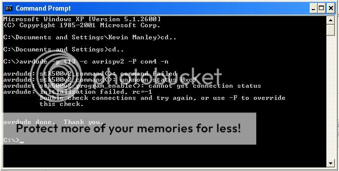

I'm running power to the board through the board's positive battery contact. Same with ground. Any idea what's going on or how to fix it?
Thanks,
Kevin
Thanks Tido for the awesome work. I can't wait to play with this. While I'm sourcing parts, What is the current crop of drivers that are flashable. I've looked on Kai domain and seems the 105c boards aren't available anymore.
They do have these boards though: http://kaidomain.com/product/details.S020074
I can't tell what microcontroller is on the board though. Anybody used this with success?
There's the 105c from Illumination supply that seems to have the Atmel on it.
https://illuminationsupply.com/8xamc7135-28a-selectable-mode-driver-p-45.html
I'm trying to see if there are any cheaper alternatives before buying from Illumination Supply.
Oh, I plan on driving XM-L's with this if it makes any difference. I may stack on more 7135's to run it at even higher current.
Thanks!