it could be because of the type “dupont” cables? If you can, try soldering short wires 22AWG and read the results
Thanks!
I have changed the cables, and it helped a bit, i have strange problem there I’ll have to monitor.
Sometimes it is okay, but sometimes it shows me wrong outputs, I think that my DMM has died.
or maybe a just new fresh battery for your dmm ?
Does anyone have a decent and cheap source for 8-pin SOIC clips? I know where to get my programmers from (Fasttech) but the cheap (like $3) SOIC clips have dried up on eBay :(
I have This one from ebay , pretty okay to me.
Sometimes have to wiggle it a little when not working the first time, but has good grip and at least until now very relieable to me
Wires have to be redone to,use with the fasttech programmer. I desoldered the included wires and used female to female dupont cables for it.
I simply got one from digikey. Not what I’d call cheap, but at least it shipped fast and it works.
… though if you find any cheap clips, it might be nice to get some extras. ![]()
The one I got from digikey was $11~ + shipping I believe…only problem…it wore out after about 50 flashes (I wasn’t very gentle with it either
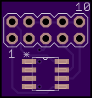
I also made a loose ATtiny programmer board, just place the IC on the pads, hold it down with something and flash it, then reflow on the PCB of the driver (The pinout only works for the ATtiny based Nanjg 105C compatible type drivers)
https://oshpark.com/shared_projects/nhVgC8ay
With the ease of a hot air reflow station might just be easier to reflow on the board, flash, then reflow on the driver
Here is the SOIC clip I got from digikey
http://www.digikey.com/product-search/en?KeyWords= 501-1311-ND&WT.z_header=search_go

Well when testing a driver, having to reflow it several times won’t be that good for the driver and atmel chip either ?
When building a light i re-flash it at least a couple of times until it meets my wishes and/or expectations. (I also have a test setup with led and cooling block to test modes on a driver, but the best test is in the light itself.)
(And this is with the led connected and everything seated in place. I just don’t solder the driver to the pill until i’m finished. (press fit or use a little piece of wire soldered to pill and driver (or in case of a convoy s2 or s3 it even can use a retainer ring when using ak 101)
Only 50 flashes?
I think I’ve probably flashed at least 200 times with mine so far, and that was all in the first week I had it. Then I got stupidly busy with other things and haven’t had time to touch firmware for a while. But I can see this clip having a very active life…
Un-soldering and re-soldering the MCU would be a major pain for me, so I have no plans to even attempt it. This works fine for me:

I need to get me some of those male/female jumpers…the ones I got from FT are male on both end…grrrr
The ones I used for the clip are FEMALE BOTH ENDS. (Toykeepers are too) Clip has male pins (4cm long in total or so) in them. They can be pulled out (at least in the one i got) and then insert them in the cables, and plugged back in the clip. (after desoldering the wires that came with mine at least)
ah…then that is what I need to get
Maybe rotate the atmel placing on that board, drill small holes thru that, and use the small size pins from dupont cable as a press fit in place programmer ? Would do the atmel placing to the opposite side of the 10pin connector too i suppose.
(That would make it one hand operable i think)
Ooooooh kaaaaaayyyy… I bet you’re popular with the neighborhood watch patrol…
Hi! I’m interested in perfect mode driver, so I bought those two:
https://www.fasttech.com/p/1002900
http://www.ebay.com/itm/171202453832
Is that enough and compatible? I noticed that the programmer is 10-cable and clip 8-cable, is the rearranging of cables the solution for this?
I’m reading the thread right now, but if these components are not ok, I still have time to cancel the orders.
One more thing is in my mind - how to use only some of AMCs? I don’t know if I understand it correctly, but I’ve read that this way the efficiency is higher at lower modes. Eg I’d like to have mode 33% in 2.1A driver, which uses only 2 AMCs to deliver the power. Is that a software or hardware hack?
I haven’t used that particular clip or cable, but I think that’s the same firmware flasher I have. I got a splittable ribbon cable from fasttech and a clip from digikey, and have been happily making my own firmware since then.
To use only some of the 7135 chips, you’d need to rewire the driver and modify the firmware, to let you control 7135s individually (or in groups). If I understand correctly, you’d need to connect each set of 7135s to a different pin on the MCU, and then do some magic in the firmware to actually use them. And you’d only be able to use PWM on one set of 7135s at a time, if you’re using an attiny13a.
However, if you split the 7135 chips into three groups (1, 1, and the rest), you could probably set it up to do the following:
- low mode(s) via PWM, 1x7135 chip, up to 16.666% power (or 12.5%).
- medium mode(s), no PWM, 1x7135 or 2x7135 chips, at 16.666% or 33.333% (or 12.5% or 25%) power.
- high/100% mode, no PWM, 6x7135 chips (or 8x7135).
This is pretty non-trivial to do, and I’m not sure which driver boards would be most compatible with the idea. But you might be able to do it by cutting traces and adding some extra wires.
It’s certainly a lot easier to just use all the 7135 chips and control the output via PWM and firmware, at the cost of some efficiency.
yes but how many different drivers? The issues arise from the smaller drivers (especially the tiny10’s) that have components places so close a stock clip cant fit, then you have to file down the teeth of the clip and that shortens the life dramatically. Another issue is on a nice cleanly built driver its easy to make a good connection but when you start flashing drivers for other people that are hand soldered and not the cleanest with excess solder on the pin’s that starts to shorten the clip’s jaw’s life very quickly.
I took the advice of RMM and plan on my clips lasting ~100 flashes, I order a new clip the second I think the current one is starting to give me issues (I’m on my 4th!) so there’s no down time.
My in-place programming 17DD’s will be here today, they dont require being removed from the light / pill to flash and dont use a clip, connection is made from the bottom of the board using a custom made header connector. If it works as expected I will be switching to using them in all my lights. They would really have been nice when setting up my S6 and TC300 because the FW took several times to get just right (because testing on the bench didnt do much for dialing in the mode levels when the lights run at >10A once assembeled, the PWM_LVL’s all needed changed to get the levels, and steps between them, where I wanted).
All in all for personal use only its not a big deal but if you plan on doing this commercially at all (even small scale /just for your friends) its nothing short of piss poor planning on your part not to have a spare clip on hand and at $4 you may as well have a spare USBASP as well, thats what I do. On a related note I much prefer flashing my chips on mt WarHawk programming board (at least till my new drivers get here). No need to solder to the board, just hold it lightly in place with your finger while you hit enter (if its a brand new chip you dont even have to do that, just set it there)
I wanted to mention this publicly (I’ve been working on it about 2 weeks now)-
I have a new programmer in the works, it’s an all in one unit that has a USB cable to plug in to the computer (not just sticks out of the side of the USB port like the little USBASP’s). It has a built in ZIF socket as well as a 10-pin header connector for a clip / my custom header for the in-place programming design. It’s built using only parts stripped from a $4 USBASP plus a $2 ZIF socket.
I’m debating how to do the header connector, as stock:
2 4 6 8 10
1 3 5 7 9
which wold make it so we have to wire it up ourselves or if I should make it so an unmodified ribbon cable can be plugged in and already have the correct pinout for our SOIC8 chips. Any input there?
Make it SOIC8 pinout… nobody likes to wire up cables. Or, even better, put both headers on it.
This looks like fun. Tido made it easy with all the comments. I should have the modes I need if it all goes right (yeah right). Need some clips so I can table test this before assembly. I’m using PB4 as the pinswitch so that should be pin 3 on the tiny13a? He’s even got alpine distress signal xd
I’ll compile it and see how it goes…