Yeah, no one is saying that the driver is advanced by any means. It is a crude driver for sure but it is effective and with the fantastic Narsil firmware for 90% of people it is more then they will ever need.
Exactly! Simply my untreated perfectionism does not allow me to use the flashlight quietly … ![]()
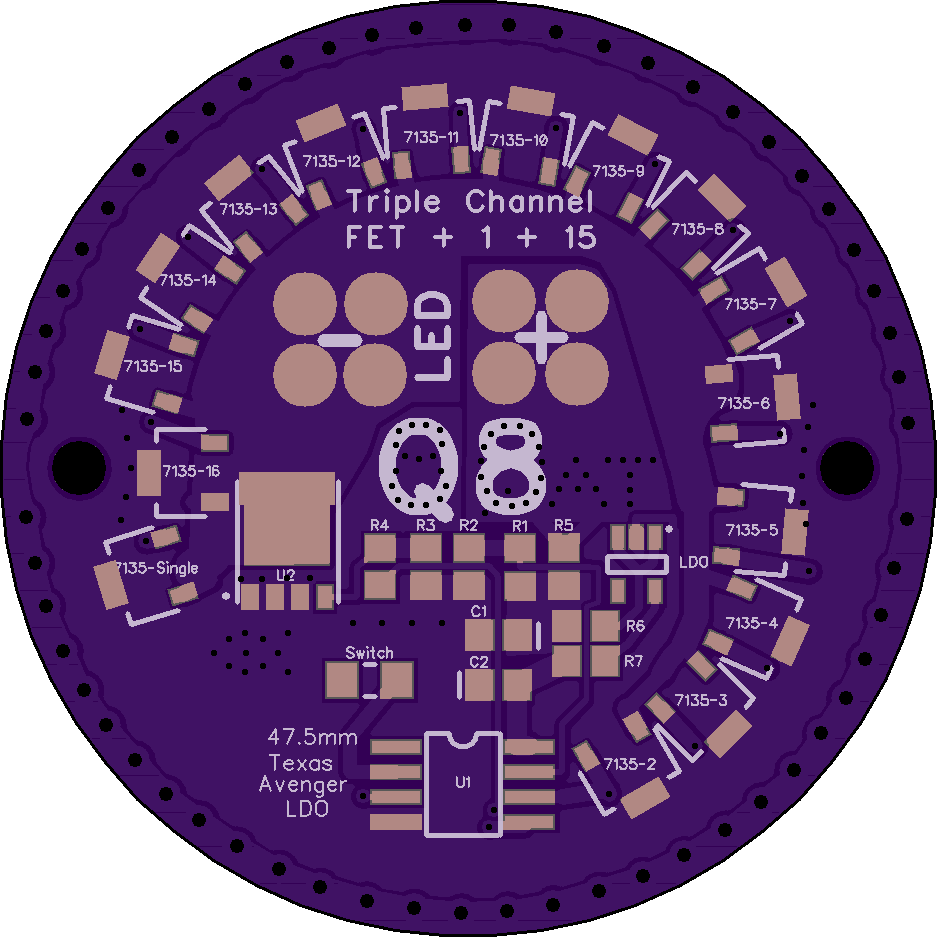
Well, as long as we’re on this discussion, I have to admit, I’d have liked for the Q8 to have a triple channel driver instead of the more “primitive” FET +1 AMC7135 so that most (if not all) the middle modes could still be “regulated” for better efficiency. That discussion did happen at one point, but the decision was made and we’re still going to get a nice light out of the deal, perfectionism notwithstanding.
Agreement here from the “sedan with cruise control” section. Hoping to see people documenting what’s needed to make that sort of change.
I’m delighted that the actual Q8 is expected to be such a good foundation piece of hardwre, one that people can dream about building on.
OP updated with:
+ the missing measurement.
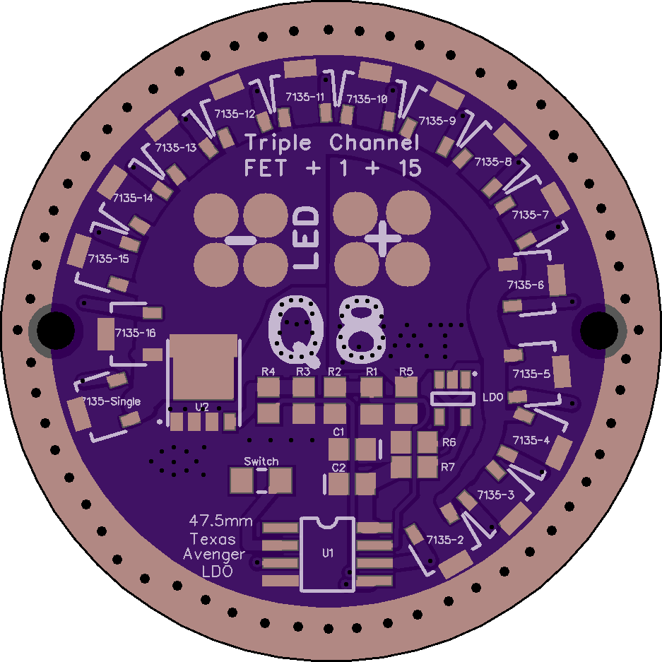
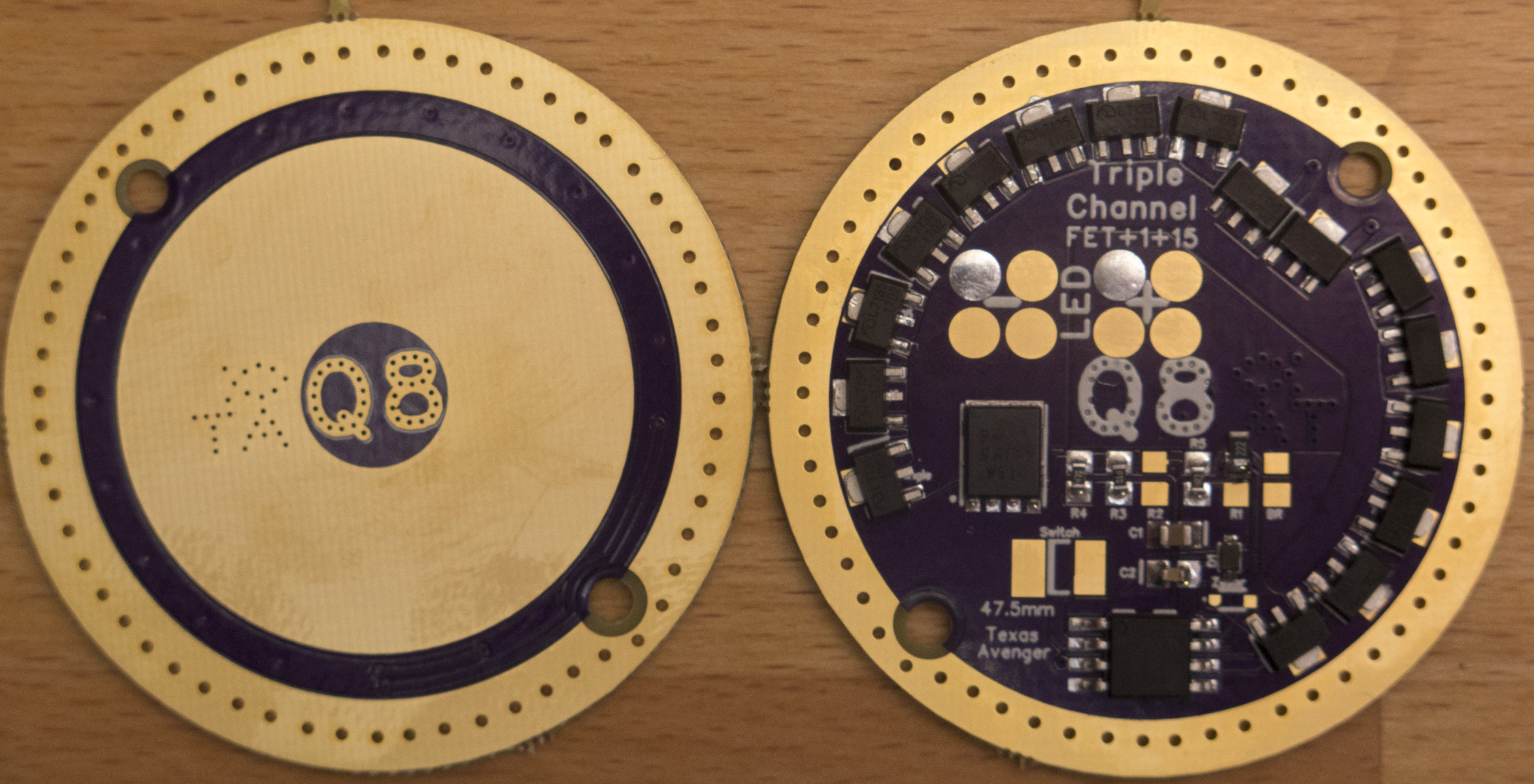
Driver diameter around 47.5mm, positive ring OD 31mm, ID20mm and from the driver shelf to the base of the ledge is 15mm. 39mm for the mounting hole spacing. They are 2.75mm holes for 2.5mm mounting screws.
and edited it in
Thanks for keeping this thread alive and attracting people’s interest here.
Copied from the TA thread:
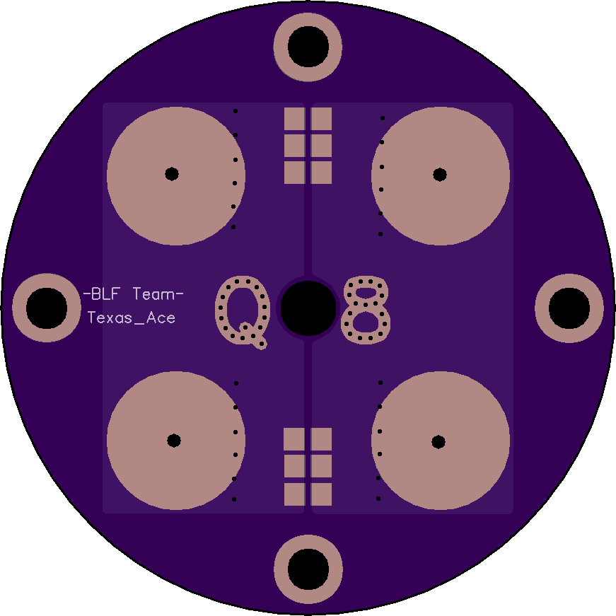
I went ahead and made a driver for the Q8 based on what I know so far, not sure if all the 7135’s will clear the mounting tabs but if you leave off 7 & 9 it should work. I don’t think it will short to anything but the ground pad, which is fine. I won’t know for sure until the Q8 is in hand though, which is why I had planned to wait until then to make a driver for it.
The extra width on the pcb made it a bit easier then I had feared, plus the mounting holes are further out then I thought, so the combo was that I was able to not cut the 7135 trace which made things much easier.
https://oshpark.com/shared_projects/dLJPLErg
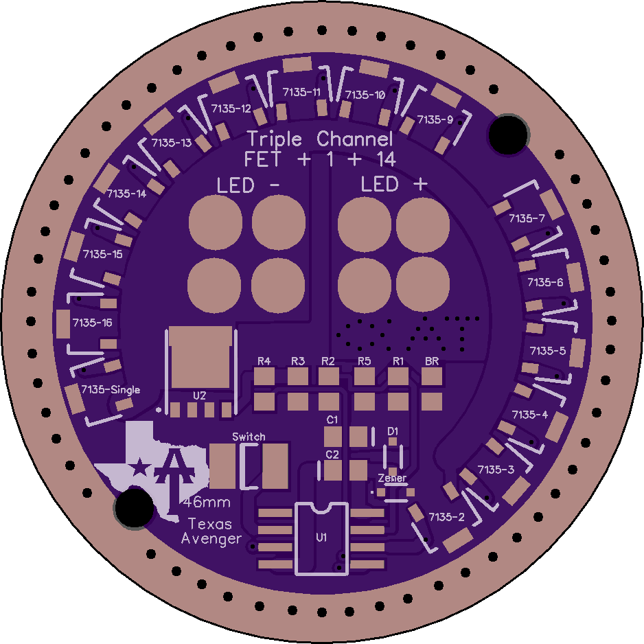
Overall it should bolt right into the Q8.
The FET+N+1 board looks like a nice improvement for the modes between 350mA and ~8A. Which, of course, is what will probably be used the most on a light like this. ![]()
I did a redesign of TA SRK driver for the Q8 yesterday,
just when he posted his layout here, because I asked him earlier if he could do it
I did a lot try and error getting used to Diptrace, but I thing the board came out nicely
Maybe doing a 2S/4P or 2S/2P if someone comes up with an extension tube for 50.2 or a solution for 2S/2P operation
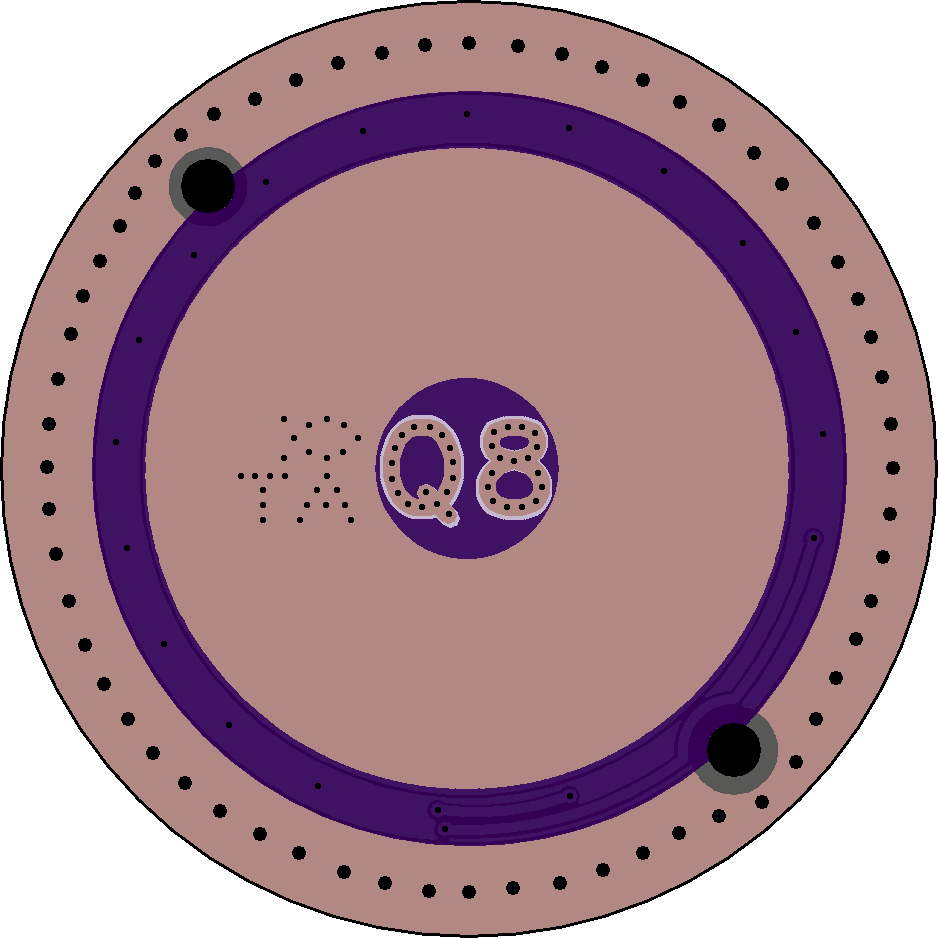
The latest version is ordered from Oshpark
I will send the driver to djozz as soon as possible to test out with his prototype
when he gives the OK that it fits I will publish the board
v2.2
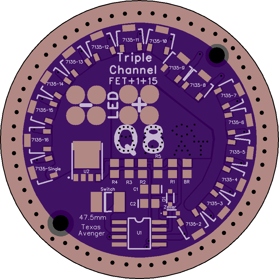
depending how much space the Q8 really has it is possible to squeeze a few more 7135 on it but not really worth the time
While you’re at it, any chance of updating the battery-side logo? ![]()
![]()
Yeah that would be awesome!
Yeah the constant current at medium levels is the biggest improvement
Of course you the used SIR404 FET is also nice
I got a nice notice from Oshpark
“Hi! We had some free room on one of our Super Swift Service panels,
so we took the opportunity to give you an upgrade.
Your affected orders are:
- Mw4NVnEJ - Q8 PCB v2.2”
SWEET! ![]()
2S/2P board designed
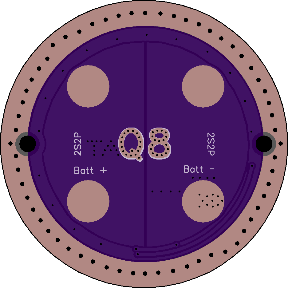
untested can say if it fits after djozz tested it
I have been thinking about this and there are a few issues. The first and largest issue is that we have no control over how the cells will line up with the driver, making this much much harder to do if the driver is screwed down. Almost impossible if screwed down.
The drivers will most likely need to be press fit / glued in place in order to line up with the cells properly.
The V+ and ground pads need to be isolated and the other 2 pads electrically neutral but connected.
As it is the V+ and ground will short out to the other 2 cells, which would get real interesting. Kinda curious if the copper trace would melt in that situation.
The spring pads also look pretty small and pretty far out, are you sure they will line up with the cells? Seems like they should be a lot closer to the center then that.
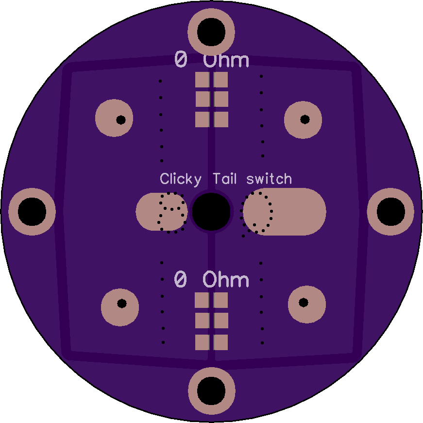
Interestingly I discovered by mistake that 0 ohm 1206 resistors actually work as fuses if you short out the cells. Long story short, I used then in the tailcap of my mega M6 build and when I was putting it together and mistakenly mis-alinged the tailcap while trying to get an amp reading.
Well there was a spark and then the light would not work anymore. After troubleshooting for way longer then I want to admit I found that both of the 0 ohm resistors had blown and acted like fuses. Interesting thing to keep in mind.
Why should there be a short if the contact board in the tailcap only connects positive and negative terminals of the Battery but not to the body
The driver gets positive and negative from batteries
If this is used you have to glue the tube to the head to hold in a fix position
and modify the tailcap bpoard to be electrically isolated and be able to laod the Q8 batteries in there
yes the battery terminals need to be that far out 19mm center to center 7mm diameter
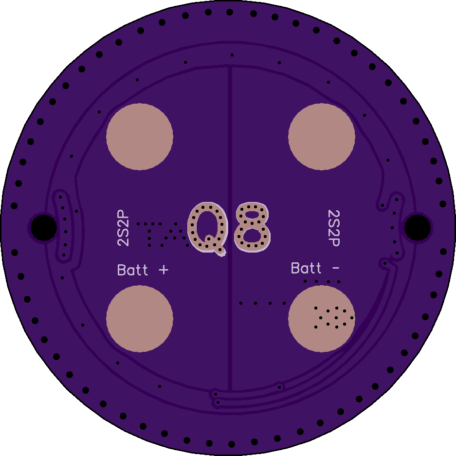
I missed the 2s2p, I was thinking 4s1p as it would be better for every situation I can think of. For 2s2p this would be correct.
Although honestly I have had very bad results trying to use the 7135’s with a high output 2S light, it tends to be luck of the draw weather they live or not. I ended up giving up on them and just using a plain FET only setup for 2s and 4s lights I would not want to even try to find the bad 7135 with 16 of them to go through.
There was a 12V capable 7135 replacement posted recently that could work for this.
first Q8 TA board buil, but djozz is on holiday till friday so can be tested next weekend