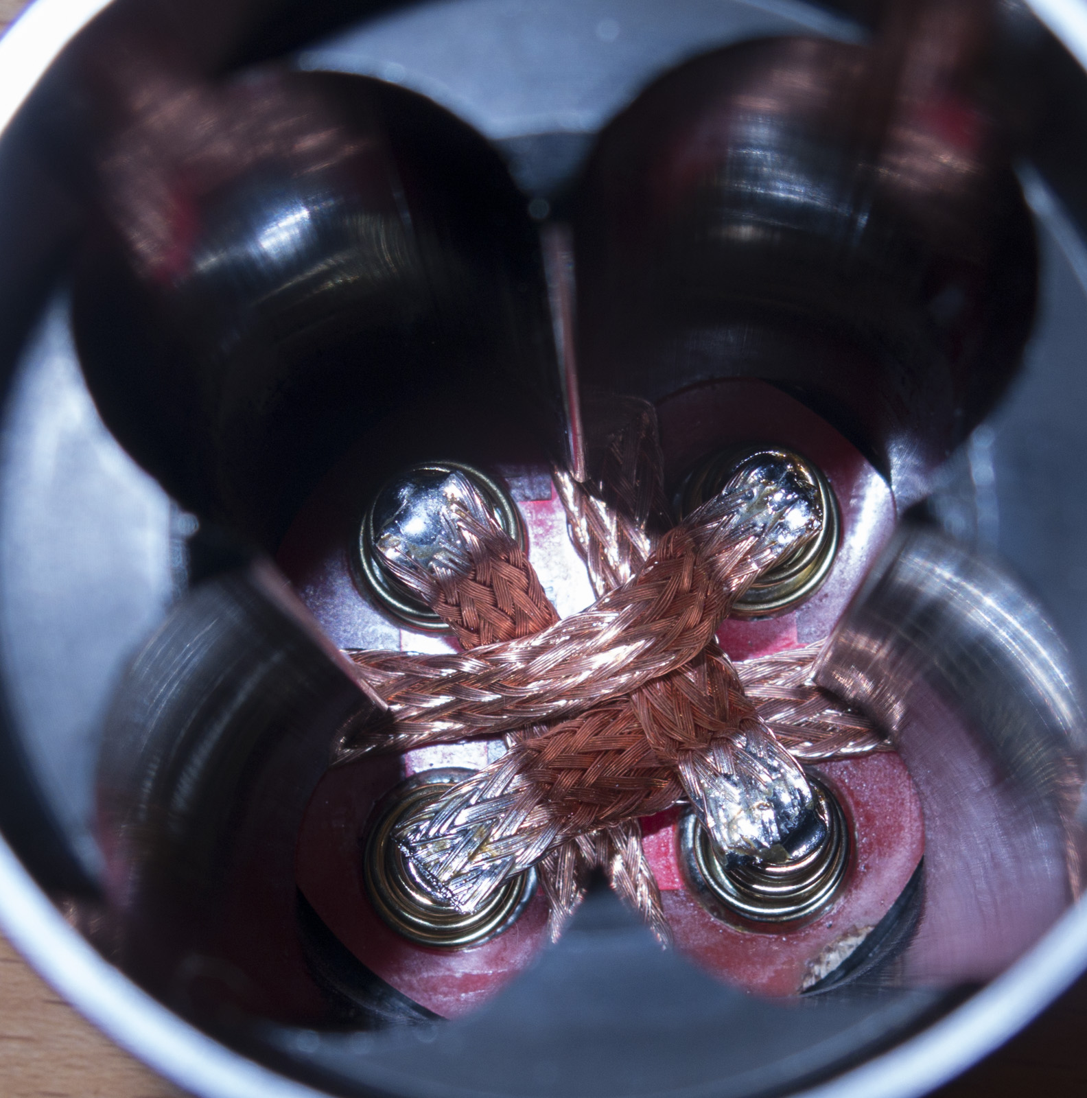
One continuous loop where the the two ends would meet could be soldered some where between the springs, would eliminate all the frayed ends. ![]()
Well, i haven’t thought about a possible strand coming lose and making a short on the other side of the tube… I guess i should just tin the ends.
It would also be possible to have each segment go from one screw to the next making a bridge over the spring in between. That way all ends would be stuck under the battery tube. It would require slightly longer screws i think.
Does anyone have a source of round copper disks suitable for replacing the tail PCB?
I don’t really trust my ability to cut a circle out of copper sheet and end up with a flat disk, without warping it.
But the simple “take copper disk, add four springs and screw holes” replacement for the tail PCB seems a no-brainer simple upgrade.
What do you think a 0.01mm2 strand would do for a short against 4 high drain cells
It would simply melt like a fuse or bond wire, causing maybe some marks on the battery shrink tube
This copper braid not soldered would never break in a flashlight
Careful with those “never”s, they tend to come all too soon. ![]()
He’s got the braid over and back down, every time the spring is compressed hard the braid folds hard on each side of the spring inside the tube battery well, it’ll break, and it won’t take all that long.
PS, yeah, Google: round copper disk - Google Search
Just asking in case anyone has already done the digging to identify the source we need for the Q8
(or for the next flashlight to come from this process)
EDIT —- this look right? Disc 45mm Blank 24g Disc Circle Metal Blanks Shape Form - Etsy
(that’s for quantity five)
The braid wont be compressed its an arc when the spring is at full lengh, when the spring gets compressed it will move a bit towards the tube, but mainly it will increase from 6mm to like 8mm to compensate the reduced lengh
flex, high heat, flex, high heat, flex, high heat, snap
Cannot tell you how many lights I’ve pulled fragments of broken braid out of… not a single one of my make, I never use it.
Pure and simple, this braid is designed to wick flux, not carry electricity. Richard tried it, found it failed, he too shifted to Turnigy wire bypasses. There’s a reason, the braid breaks down.
Anduril is putting on a show over here, my Q8 D4 and D1 are all in lightning mode, the D4 has green XP-E2 emitters, it’s pretty wild. “major storm” lol
Guess I have to run flash Q8 number 2 so it can join the show. ![]()
4 lights in the party now. ![]()
I wonder what percentage of copper is in those copper discs.
Great find!!
PS: It is in 24 gauge, around 0.5mm thick
you are right about fluxed braid for desoldering, the flux makes it break
Also if its too short and cant compensate the length change with changing its diameter it will fail
But braid for electrical connections is another thing, if its long enough it can withstand high mechanical stress for thousands of hours without breaking,
like big machines that are mounted on shock absorbers are often grounded witch copper braid
The braid should not get hot at all
Remember that Dale posted numbers on the disk mod and IIRC, they were not anywhere near what he got for the spring bypass. I’m on a phone right now so it’s hard for me to find or I’d post a link.
> disk mod and IIRC, they were not anywhere near
I wonder why a copper disk would have more resistance than a copper wire.
But there’s a lot I don’t know.
Hm, there are a lot of kinds of copper: Innovations: Introduction to Copper: Types of Copper
I tried asking that Etsy seller what “first grade” means — though it’s a small shop in Mexico and they may not know.
The PCB the original springs are mounted on has thick enough copper traces that there’s not a lot to be gained by using a copper plate. I only saw 93 lumens by doing it. Not even noticeable to the eye. Quite a bit of trouble to go to.
The spring bypass saw over 1200 lumens increase, so that’s the one big thing to do.
And for the record, Anduril and the 4 XP-L2 emitters are having some discussion as to whether or not they like me doing this to them. ![]() One of the 4 emitters is dim, not making the output the other 3 are. And Anduril is acting up inconsistently, so there are some compatibility issues somewhere.
One of the 4 emitters is dim, not making the output the other 3 are. And Anduril is acting up inconsistently, so there are some compatibility issues somewhere.
I’m glad to see I’m not the only one to have found the proper layout for durability ![]()
But what’s that about the flux? I only had desoldering braid on hand but I don’t know if it’s fluxed or not. I probably won’t change the cells often enough for it to ever break but I’d rather do it well.
Not familiar really with flux and braid as I never use either. I said flux, I meant that the braid is meant to pull solder off boards, like a sponge. It’s woven loose to allow solder to flow up into the crevices. Not ideal for carrying current. Turnigy silicone coated wire is made for current, the silicone will protect from a short if a solder joint breaks, or there is the possibility that it will. The braid? It goes to pieces inside a light. Perhaps if you are an electrical engineer and know all the in’s and outs, that’s great, but most of us aren’t and some of the applications need help, so using a wire is the safer and more robust way to do it.
I’d like to find out how much current this de-soldering braid can carry as compared to a 22Ga or 20Ga Turnigy wire. I figure I’m pulling close to 30A, so each cell would be doing 7.25A, how well would that loose braid that wasn’t meant to carry current do?
Remember, the big machines that are grounded with braid are grounded with a 1/4” thick 2” wide strap of very tight braid, it’s like it’s solid, this stuff? yeah, not so much. Grounding straps withstand vibration and long course movement, not short abrupt angles. And repeated heavy flex, you do what you want of course, but nary a one of the 400+ lights I’ve built have braid in them for a reason. Richard learned the hard way, replacing spring bypass wires in lights when he had not the time to do so. And so it goes.
We told you before not use desolder braid
Desolder braid is made from a single flat strand, and cant change its diameter when you try to change its lengh, it bends and if it is fluxed its even worse as there is solid stuff between the copper strands
While braid for grounding stuff is made like a tube then sqeezed flat
Just think of it like the shield around HF wires, when you push it back it widens its diameter
This way instead of bending around corners it simply changes its lengh by widening its diameter
As far as i can tell the braid i’ve used and linked to is for electrical ground purpose, not desoldering. It is like a very tightly knitted ‘sleeve’ or tube and will change width/diameter when compressed. Strands are very thin indeed and would probably melt like a fuse.