Can someone confirm sizes, I plan to order some screws?
3X? I just got the 2.5x5’s, used them on the driver and tail pcb. No real need to take it further than that. Worked fine with my XP-L2 light up to 10,212 lumens so I suppose that’d do for most anything.
My feeling is that you have to work on your calibration (for this colour temperature) or integration quality Dale, 2500lm/led is about the max for a bare W2 (calculated from Texas Ace’s calibration, measured on a 5000K led), that is without optics and lens losses.
What you got is bout as good as it gets. Batch 1's are all over the place - some clearly cut down, so on some, M2.5 x 4mm are used or cut down as low as 3mm lengths. There's variations in threaded hole depths, etc. Batch 2 are way more predictable.
Today I'm getting my batch 2 brass replacement screws: M4x10mm and M2.5x10mm  .
.
Someone asked earlier about the oil - the oil is from the machining process. Normally it's cleaned off before shipped out but at these cut rate prices, the cleaning step is skipped. If you've seen episodes of "How It's Made", cutting, machining, drilling metal is usually accompanied by high amounts of oil, called "cutting oil". Not sure if I'm right on this, but I think it prolongs the life of the cutting instruments, makes the cuts easier and smoother, etc. I use it myself all the time now with my bench drill press when drilling or machining aluminum, brass or copper. Definitely improves the speed and smoothness for me.
Thank you all :+1:
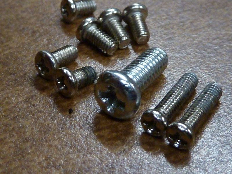
Let’s have it all at one place ![]()
The Miller you can add it to first post if you want.
First batch (if I’m right):
driver: M3×5mm *2
tail pcb: M2.5×5mm *4
reflector: M4×8mm *1
mcpcb: M2.5×5mm *2
Second batch:
driver: M2.5×4mm *2
tail pcb: M2.5×5mm *4
reflector: M4×10mm *1
mcpcb: M2.5×10mm *2
DB Custom
I know there is no gain in replacing other screws, but they have damaged heads so I would like replace it ![]()
Today I got my 2.5 mm brass screws delivered (very fast 11 days shipping), but also disappointing cracks in the screw heads.
Would you go the negative feedback route?

My 2nd batch tail pcb screws are M2.5 x 6 mm including head.
Ask for new screws , or refund . Seller is just a seller , and not the factory that made them (and had QC issues).
XP-L2 and XP-L W2 are different creatures. I have both, they are obviously different. The XP-L2 is along the lines of the XP-G3, the inverted die with no bond wires. The XP-L W2 has visible bond wires and the dots on the phosphor not seen on the XP-L2.
I was as surprised as anyone to see that 10,212 lumens, believe me!
When I re-flowed the XP-L2’s onto the Q8 MCPCB I didn’t realize the thermal pad was sunken. I didn’t add solder paste so I ended up overheating the LED’s. I think that’s why I am now “only” seeing 8728 lumens instead of the 10,212. If I’d had more of the XP-L2’s I would have used new ones again after I cleaned the MCPCB and used a solder paste mask to get the right re-flow. I re-used the LED’s that had started glitching, and here I am.
Now running bistro-HD on my Q8. Actually have been on and off for awhile, but now sharing a working version:
https://budgetlightforum.com/t/-/44344
It runs fine. Long click off, no new e-switch specific features yet like on-press shortcuts or lockout. Not that it matters for the Q8, but it fits on an attiny25 still. Download includes precompiled hex and click to compile and click to flash scripts.
Thanks for gathering the info. I like tables….
| Num Screws | 1st batch | 2nd batch | |
| Driver | 2 | M3×5mm | M2.5×4mm |
| Tail PCB | 4 | M2.5×5mm | M2.5×5mm |
| Reflector | 1 | M4×8mm | M4×10mm |
| MCPCB | 2 | M2.5×5mm | M2.5×10mm |
This is what I have, differing with the 1st batch MCPCB screws:
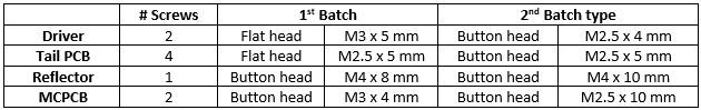
Batch #1 screws:
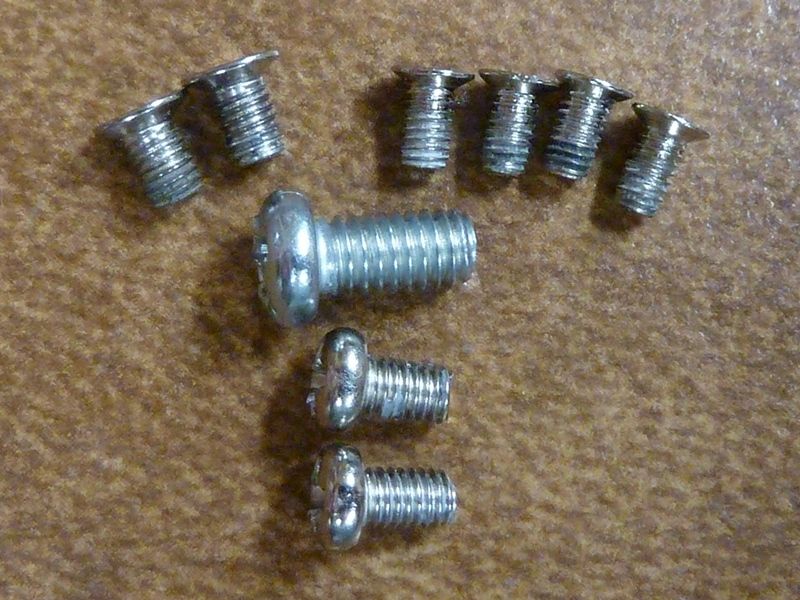
batch 1's I've collected/replaced:
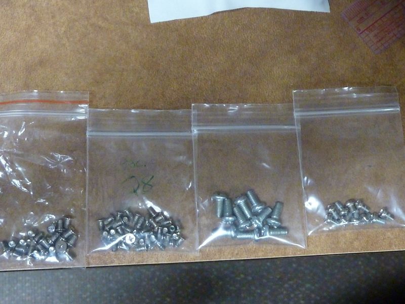
Batch #2 screws:
I find it extraordinarily amazing how a year’s worth of speculation and conjecture culminates with a finalized item that is scrutinized not for it it’s excessive delivery of refinements but for the simplest of choices… the screws used in assembly!
Lot of this stuff was already posted, just hard to find, and not centralized and confirmed. I didn't organize this myself til just now. I forget what I posted, what I took pics of, what I wrote down notes for, etc.
But if it's the main thing to critique, that's not bad...
> simplest of choices
My concern was the way the PCB was warped by overtight screws, and the poor contact
made with the battery tube because of the warped PCB and rough metal edges on the battery tube
Changed the emitter in my Q8 to XP-L HI U6 5A3 :

Q8 to XP-L HI U6 5A3

Q8 XP-L HD 3D
I used the same battery tube with bypassed springs and VTC6’s with both heads, it’s almost full moon and overcast in the images.
Understood Hank, in the first batch of 500 there were those issues, but they paid attention and corrected the problem such that the 3 Q8’s I saw were not affected in like manner. By having a slightly larger hole in the PCB of the driver, the mount screws don’t lift it or tilt it, firmly securing it to the shelf. Same as the spring’s pcb in the tail end of the Q8, the screws used mounted it securely and were properly applied.
As Tom intoned, if the screws are the biggest problem we are doing really good! Much more output than originally intended, better copper MCPCB, excellent emitters, great reflector, lighted side switch, and the driver components stick with the tried and proven values as prescribed by Del and Tom, so the successes here are larger than the failures, lessons were learned and adaptations applied. Win win, great overall interface with a known Manufacturer and certainly an encouraging joint effort.
I am trying to make a lantern extension for the Q8, does someone knows the thread size of the bezel?