Yeah, that is about right. The hole in the center will really have a small effect on the overall cooling. It is worth mentioning but not much more then that. If nothing else it will show that we are willing to give up things when needed if it is mentioned and not pushed.
I'm more concerned about the anodized surface of the shelf than the hole. I don't think it's a good thing, but I'm not sure bout it either. The 30 sec droppage was reduced a little after assembled with the OSHPark driver, but could be because of better and less thermal grease that I used. I intentionally didn't sand down the bonding surfaces to keep it stock, but the bottom of the MCPCB is rough finished for sure. Also doesn't make sense to make the MCPCB so thin. I'd like to see another 1/4 to 1/2 mm added.
For the hole, I can't think of any reason why it's so big, unless they planned on using those two unused holes in the MCPCB. Think it was just from a change in plans/design of how to run the wires, because those unused holes lie over the big center hole in the shelf.
Haven’t you heard, it is not possible for too much thermal paste to reduce heat transfer : thermal paste
:person_facepalming: :person_facepalming:
The ano on the shelf is not helping anything and is an easy fix as well. That said I doubt it will make a massive difference either with that much raw surface area in contact with the shelf.
I do totally agree that a thicker copper MCPCB would be important and a better finish should also be sought but most important is it being truly flat.
The Big hole was to give way for two screws, holding the reflector on the MCP. It’s in the first cut away pic they sent.
At least that’s what I guess.
The big center hole in the shelf won’t reduce the heat flow much, as long as there is metal behind the LEDs, but it does reduce the heat capacity somewhat. It will heat up a bit more quickly.
Nice pictures Tom and thanks for the update.
Looking good so far. Is there a reason it was not sent to you with the Q8 driver that you installed in it, Tom E?
6000 lumens is kick-ass and I would say more of a drawcard for potential buyers than 4000, I’m really impressed with 6k! I really hope thorfire makes the improvements you have mentioned and we get a light for sale that performs as this did (with the improvements you made/want).
Cheers for update - this light was the very reason I bit the bullet and joined. It’ll be worth the wait to get every single part and the performance exactly how we all want it.
Edit - it seems crucial to have a bypass on the -ve springs to get max performance. I know this has been discussed before in this mountain of posts, but if double springs are used will that ensure performance up-to-par with bypassed springs?
Or do they get bypassed as well ? Sorry if that’s a dumb question :person_facepalming:
I absolutely love the ramping software, it’s simply amazing. I still don’t like the reflector, it looks like it can be opened up more.
Good job Tom and yes I love that indicator
Superb
Excellent
I too wish that the power button light indicator stays…
+1
Would be sweet.
+1 for the lighted button,
And I think too the MCPCB could be thicker. The shelf thickness is good but with maximum 6-7mm hole in center.
I don’t really care springs because I do bypass easly
Reflector should be bigger, and more centered
All other things great!
We have to see about that lighted switch, indeed would be very swet with all the cool features Narsil has for it!
Reason for the driver was that there was some confusion. Our ThorFire contact is not technical - the engineer responsible (poor in English) said our driver was not production ready - we don't know what he meant, and he no longer works there, so we never found out why he thought that. Since the parts were changed (different MCU, different FET), I was speculating it was costs/availability. The process for the driver has been re-started with a new engineering team so hoping we hear back soon with details. The MCU they used was unmarked and didn't match an ATMEL AVR or a PIC I know of - the ground and VCC pins were not the same as any MCU I'm familiar with.
Double springs have less voltage drop than single. The Fenix PD40 is an example of a high quality, high output light using double springs on both ends, and advertise it as such here: http://www.fenixlight.com/ProductMore.aspx?id=1155&tid=9&cid=1# in this picture:
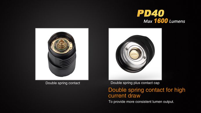
Usually a bypass will still be better though, but we thought, as others have, offering the light shipped with double springs will be an advantage for those without the skills or time/effort to solder in 4 bypass's, same as decided for the BLF X5/X6 and Cometa, etc.
Also taken from a Ronin42 post in the X5/X6 group buy thread:
here is a quote from the Manker T01 review:
“ Inside the tail cap we can see something I’ve not seen done before in a light – dual cathode springs on the cathode PCB. The main spring is super thick for optimum electrical conduction. A second, thinner spring rides just inside it for increased flow of electricity. Think of it as having a factory spring mod. Both appear to be gold plated.”
So, not sure, but maybe Manker originated this, or Fenix?
Another +1 on the lit switch. With that included you could genuinely put the q8 next to a light twice the price and not know which was which. Even if it’s a small cost I think most would appreciate it.
If double springs can be standard I’d be happy with that over needing to add a bypass, there wouldn’t be much difference in performance and it saves a fiddly soldering job for those with fat fingers.
Great work. I'm definitely with TA on liking the tighter beam spot on the SRK, and could care less about rose petals, but these are preference things.
Also, I don't think the shelf hole is a big issue. Sure it could be a little better, but it probably represents 20% of the board area. Area is pi*(Ro^2-Ri^2) So if you have a hole half the board radius, it's still only 1/4 the total board area. And in the end the heat has to flow outward anyway. If there was a hot component over the hole that might be different, but there's not.
I wrote that and then I took a measure.. wow, I was close. I get that the hole is 18.8% (plus or minus a little) of the total area assuming the board goes to edge of the lower recess. So already about 80% of the area is covered.
Please add me to the list ![]()
I hope the final product is as expected.
Please add me to the list.
This looks terrific ... nice work to all that know what they are doing! ... I know I don't, but I think I have $40 
Agreed and well said. If it’s a no-cost ‘fix’ then fine, but not much more can be had here. Same goes for the anodizing here.
The driver is the more important concern; I might be able to get a little help for technical Chinese-English translations as there’s a nice guy on a dashcam forum who works doing development stuff with those directly with the factories. He’s very busy though, so I’d rather we not bother him until we’re really stuck. Which hopefully won’t happen ![]()
I’m intrigued with the double springs- one for strength and one for current-carrying; that seems to be a more practical approach for manufacturers than hand-worked bypasses and has much less chance of shorting out. For the easy gains to be had I wonder why more manufacturers don’t do this? I’m still PO’ed with my A6 changing modes when bumped and this approach should eliminate that. Those wanting to bypass still can so nothing lost, only gains ![]()
It seems we’re going to wind up with a light that exceeds the design expectations- I can’t recall seeing that happen before! Now to wipe the drool off my keyboard and begin chanting my “Patience” mantra….
Phil