I have been on the border for a while on this light ![]()
and now there’s xintd X3 that also equally look nice to this.
xintd body and color + JM26 reflector style/size, that would be “just take my money” combination ![]()
hi TurboBB: you may need to update your review again, because apparently there was a production change: I just received the first of the two JM26 I ordered- this one from CNQualitygoods…mine too starts in low mode, also, there is no 2-second delay in activation; the first short press on the switch turns it on on low mode. I guess I have some concern about accidental activation, but the flip side is that it comes on right away. Another puzzling thing is that the Shadow logo is printed CROOKED….as in not aligned…the letters aren’t printed (etched?) straight. Wonder if I got a “fake”, or just that someone on the production line was in a hurry? BTW: re:OP reflector: I emailed Shadow, they said that the light definitely does come with either smooth or OP (customer’s choice) and that, if all else fails, OP reflector is available as a replacement part for $2.80 USD……the email from Shadow said that the reflector was “easy to install”, but the stainless steel bezel seems to be glued on….?
@steve - will do. I just got in Lighten7's Max X3A and it has the new UI that you described. As for the laser etching not being perfectly aligned, that's normal as I've noticed it on a few of the Shadow lights so I wouldn't be too concerned. The SS bezel was a little tough to remove but definitely wasn't glued (perhaps it was just my review sample).
J) hey folks…it seems like I’ve discovered the reason for the disparity between the factory-spec UI (2-second press to turn on, starts in high, goes to med then low) vs the UI that a number of the Chinese retailers (Fasttech, Wallbuys, CNQG) are now shipping (comes on right away, starts in low, then goes to med & high):
I was talking to Jason at SBflashlights; it seems that the JM26 and its 3-emitter clone, the SL3, were designed as a collaboration between Jason and Shadow: the original UI is his spec, and he says that he had an agreement with Shadow, in which they would not be sold by anyone else, that is, he was given exclusivity.
It seems like Shadow has found a way around this, by offering the lights with a different UI, so that (I guess in their minds) it’s technically a “different model”, because of the UI difference. Problem is, the JM26 is sold as a “thrower”- so coming on in high is a definite advantage. Also, the 2-second press to turn on is a deterrent to accidental activation. I, for one, for a thrower, prefer the original UI design (2-second press then come on in high).
+Interestingly, the JM26s and SL-3s that Jason has in stock all have the original UI….so I just ordered one of each from him….
Just a heads up, I received mine from wallbuys today.
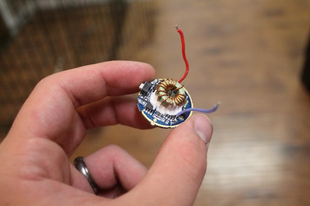
Driver is NOT 7135 based. Makes me sad, now I have to figure out how to raise the current in another way.

Thanks for the report bdiddle. I just received mine recently too. I really like the mode order (L-M-H) and mode separation. The output seems decent. I have only used a partially charged cell (4v) so far. When I charge a 26650, I’ll check current. Have you checked it yet?
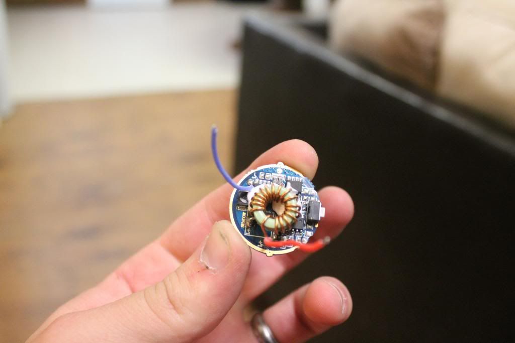
EDIT: That thermal adheasive is making it hard to picture the circuit. I’m hoping the two resistors nearest your palm in the first picture are the sense resistors. Does that adheasive pick off easily. Alcohol may help with its removal.
No, but I think it is at least 3 amps. Fairly bright compared to my other single cell lights.
That sounds about right to me. I added an edit to my previous post.
I was able to scrape some of the thermal goop off fairly easily. I’ll be trying those resistors later, right now I am polishing the led base.
Best of luck bro. Hopefully, someone around here knows that driver.
Great review, beautiful pics, but i like memory, thank you, TurboBB
Crap, one of the biggest arguments why I ordered this light is because of easy modable driver ![]()
I guess it would be best to open PP dispute because it’s a fake product…
?
It’s a Shadow JM26 with a different driver, it’s bright and has a nice user interface. Why would you call it fake?
I had responded to Sirius9’s comment this morning, then decided it just wasn’t worth it and deleted it.
I’m trying to get around to this light. I’m hoping those 2 resistors are the voltage sense resistors. I think what I want to try is to measure current, then add another resistor on top of them that is equal to the highest one of the 2 already in place. Then remeasure current and check behavior. I’m hoping it is a safe approach as I really like the driver. I just want more current on high.
Just curious, how are you checking current? I was able to get a reading by using an 18650 and a sleave, but it was a pretty hokey setup so I am not sure if I trust it.
However, adding resistors there does increase current. I think it only draws ~2.2A stock though. After adding 4x r500’s (All I have until a FT package finally arrives) gave me a measured current of ~2.6A. It was measurably brighter doing a ceiling bounce.I think I will try shorting those resistors and see if it goes direct drive on high. The inductor on the board seems up to the task……
Do you recall what the labels on the stock resisters were?
For this light, the electronic switch makes doing a tail current reading harder if you don’t have a helper. For tail, I would just hold one DMM lead against the battery negative (putting good downward pressure) and the other lead against the threads or the end of the tube if the threads are anodized.
For emitter current, you need to connect one lead to a driver output wire and one to the emitter. Thre rest of the light is assembled just the way it would be used. This is the best way to know for sure what current is making it to the emitter. I usually solder a longer 18 gauge wires to driver and run them out to an emitter in a separate flashlight head. The longer wires allow you to pull out the pill to change resistors and retest with having to disconnect the wires. You want the wires to be as short as possible to allow you to work comfortably.
I don’t think shorting the resistors will go direct drive. It will probably just allow the FET (whatever component that regulates is regulating the max current) to provide the most current it can provide. If it can provide enough, it will be close to direct drive. I’m guessing that it won’t though. There have been a lot of folks that have shorted other drivers like you are thinking. I don’t know of any cases where it harmed the driver. Plenty emitters have been blown that way, but the xml2 should be able to handle your 18650 fine if it is well heat sinked. I think you said you were addressing that already.
I need to call it a night. Thank you for reporting what you have done. That is very helpful.
Well I did add a tiny wire across the resistors, raised current enough where I think its direct drive on high. Previously swapping between a Sanyo 2600 and an NCR18650PD showed no difference, now the PD has a tad more brightness. Modes still work.
Stock resistors were r100 and r50 I think.
This may be too much trouble, but you can figure out what resistance you need by measuring the voltage across the resistors. You put your DMM on the DC voltage setting and then place the probes on each side of one of the resistors. It will be low number like .1435. The formula for calculating the current is Voltage divided by Resistance. So lets say you have 2 R082 resistors (in parallel). The current would be:
.1435 / .041 = 3.5 amps
The formula for calculating the resulting resistance of all the resistors is:
Req = 1/{(1/R1)(1/R3)…+(1/Rn)}
Personally, I say just short the resistor bank. But I don’t take responsibility if it fries your driver. I don’t think it will, but I’m no expert.
EDIT: Cross post. I see you already did. Did you try to measure current?
So before the short you changed the resistance from .083 to .05ohms. I would have expected that to get you from 2.2amps (Your stock reading which sounds real low) to like 3.7amps. Obviously, I don’t know something or maybe your measurements are off. Probably, both.
EDIT: I just wanted to thank you again. I think you figured out how to mod the current for this driver. Congratulations! Thank you for taking the risk and reporting back. When you get a chance and if you don’t mind, please try to get a tail current reading.