I managed to get one of these lights apart, a Sofirn SF36 with a broken driver. The LED is fine though, and works as a PWM sensor. It looks like an original XP-L, which is basically XM-L2 with the sides of the dome chopped off. It handles 36 kHz just fine on my DMM, but I don’t know how the actual scope traces would look.
I could send it, if desired. Either the whole light or just the head.
Toykeeper,
I did a post about building a PWM sensor:
I based this on Terry’s build.
A cheap solar cell works well but doesn’t have the resolving power of one of the diodes.
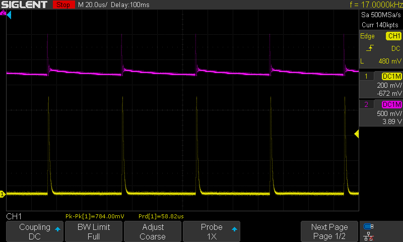
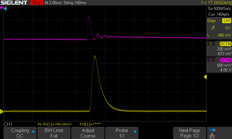
Here are a pair of traces, the top trace in each shot is a cheap photocell and the bottom one of the OSRAM BPW34S Terry found to excel at this.
This is a shot of florescent lights in my office.
This is a shot of a flashlight I tested.
The photocell has a slow V drop compared to the OSRAM BPW34S
On another note (literally) you can hook up a cheap solar cell like this one directly to an efficient speaker and you can hear the PWM on flashlights that use a frequency in the lower audio bands. You can hear it change as the PWM cycles through different modes. Who says a flashlight can’t make music?
As I mentioned at the end of my post I ended up with 5 of these BPW34 diodes.
I’d like to give away 3 of them to deserving BLFs. PM me an address (US only please) and I’ll mail a diode and a few 10K resistors to play with.
All the Best,
Jeff
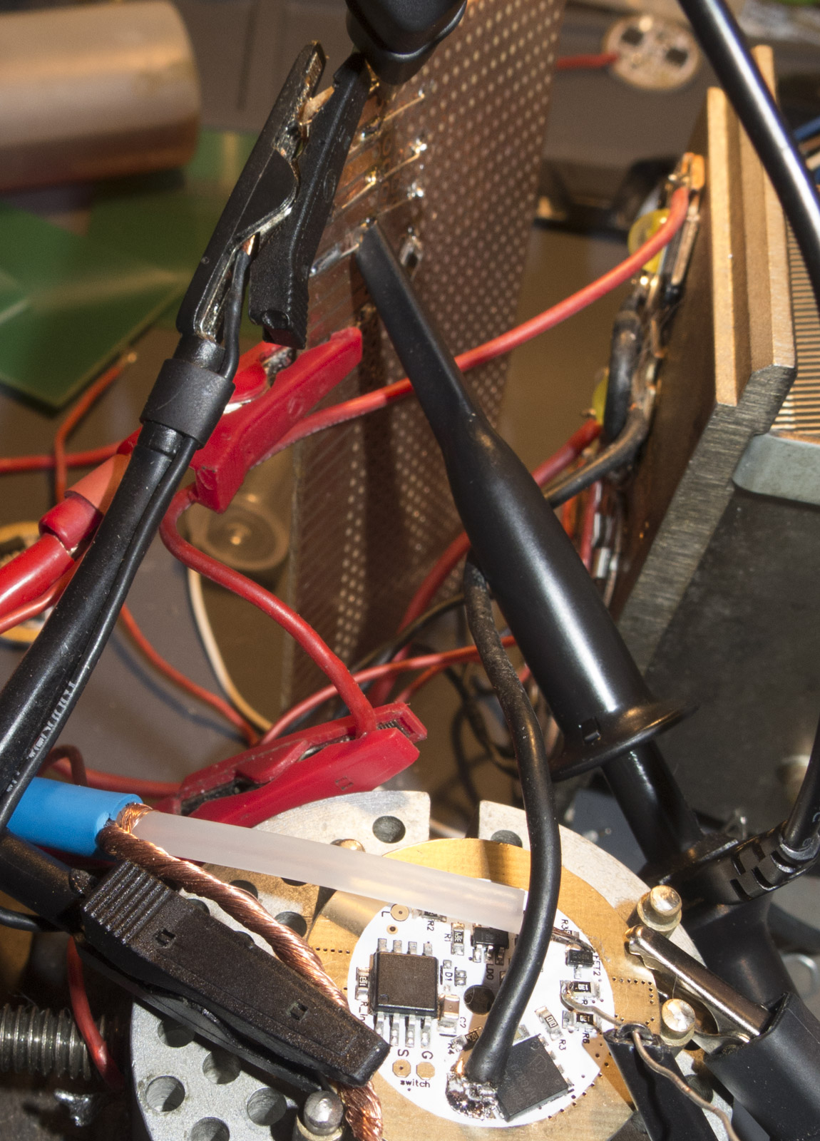
Yesterday, I received the head of a Sofirn SF36 from BLF member ToyKeeper (special thanks). The Sofirn was donated to me for testing the suitability of using a regular flashlight LED for measuring PWM. Red/black wires were attached directly to the LED.
According to ToyKeeper, the type of LED is;
Unfortunately, the results were rather poor.
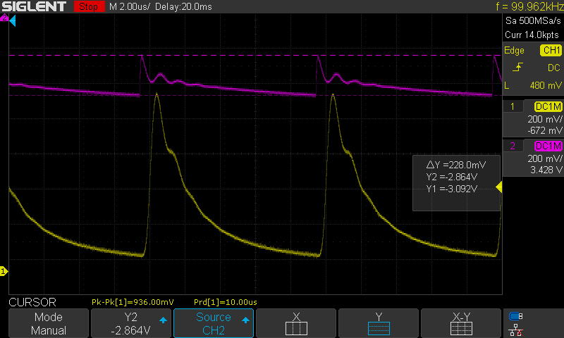
I could only get a decent waveform with very LOW frequencies. Here, I’m using a J5 Tactical V1 Pro on strobe (8hz).
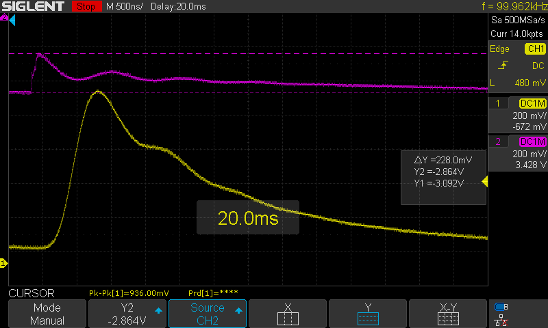
Here, we have the J5 on low (PWM at 234hz). The problem is what you see circled in red. The oscilloscope time base is 1ms. So, the total fall time for this waveform is about 3msec. That’s way too slow for successfully measuring PWM frequencies in the KHz range. Fall time needs to be less than about 5us when measuring PWM above 5Khz.
I tried several things:
(1) I measured across several different series resisters (1K to 100K).
(2) used different biasing voltages 3V to 7V
(3) I tried measuring directly across the LED (no series resistors).
Nothing helped.
Conclusion; PIN photodiodes are still the most suitable photodiode for measuring flashlight PWM. Flashlight LEDs (at least some) are too slow for higher PWM frequencies.
User DavidEF may be sending me more LEDs to test in the future.
The results were about the same. Anything below 10K ohms in parallel, and there was too much noise. I then tried 100K and 200K ohms (below), and we get a good waveform, but the fall time is still way too slow. This is with the J5 at 234hz. Trying to use the Convoy S2+ just gives me a flatlline DC level, as frequencies above 10Khz get filtered out by the slow fall time. I think we're still confined by the slow response time of the LED itself.
That’s really interesting. I wonder why the LED worked for me but not for you. I had no trouble measuring 36 kHz with that exact LED. All I had to do was hook it up to my DMM directly, and hold a flashlight up to it for measurement.
The main problem I ran into was trying to measure moon-level modes. The lowest modes don’t seem to be bright enough to get a usable signal.
Hard to say what the difference was. Whatever meter you used (and its internal circuitry) is in parallel with the LED and may have some effect on the results.
What DMM were you using? I used a Fluke 79 III, and it measured the low frequencies OK, but anything higher, and nothing.
Going forward, I will try some other LEDs as I get them.
I will be surprised if something else can work as well as a PIN photodiode.
This might be a good time to repost this YouTube video, which originally got me thinking about measuring PWM:
Terry, how does the SF36 compare to a regular solar cell?
And have you tried more than one solar cell?
I was wondering if the type of PV cell makes a difference.
Since it’s so easy to rip one out of some sort of solar powered gadget, it would be an easy source to play with for most of us.
I haven’t got a follow up post ready on my O-scope software adventure. I found that a 20KHz PWM shows up OK (well it’s noisy) on the frequency analyzer part of the O-scope software. But the sample rate is way too slow on a 48K sound card to make any sense of the waveform.
You've lost me here on what was done. You may want to add some more detail. I'm thinking this is understood by those who mod?
Is this in reference to a Convoy L6? You diss-assembled the Convoy L6 and are controlling the driver board directly?
This was your actual photo sensor? 8K ohms was in series or parallel with the OSRAM? Which OSRAM?
OK, I think we're back to the Convoy? A quick search for "Attiny" - appears to be a programmable micro-processor? You used this to control PWM output on the Convoy L6 driver board? The 6.5ohms was placed where?
OK, as I typed this up, I see you've added some more pictures - which clarifies that it was a bit complex.
Today, I received four LEDs from BLF member DavidEF. These were given to me – to find out if a regular LED could be used as a photo diode (for measuring PWM).
Unfortunately, all four could only measure PWM at low frequencies. The photos below show PWM from my J5 Tactical V1 Pro (at 257hz).
The fall time on all four of these diodes was way too slow to measure anything from a Convoy S2+ (2KHz to 36KHz).
They all had fall times from 230us (fastest) to over 2mili seconds. Measuring PWM on a flashlight requires fall times less than about 10us. Multiple ways of biasing these LEDs were tried. Nothing really helped.
The four LEDs were:
XM-L2
XP-E2
SST-90 (de-domed)
Large Generic Chinese 50W COB
Conclusion. These are not adequate for measuring all PWM frequencies typically found in a consumer flashlight. We are back to PIN photodiodes as the winners.
It is also possible that I’m missing something – and someone else can find a better way to bias these types of regular LEDs that would make them work for PWM. However, for less than $10, it’s hard to beat the OSRAM PIN BPW34S.
Terry, I’m glad the LED emitters arrived safely. Thanks for the testing! I’m a bit surprised the XP-E2 seems to have done better than the bigger die LEDs, if I’m reading right.
One of these days, I might have to get a low-end scope. It’d be really handy sometimes to see what’s actually happening inside my electronics. And maybe I could even figure out why my results have been so different than Terry’s. It’s weird that I had no trouble measuring 36 kHz on the exact same LED which showed a 3ms fall time here.