Btw: there is a (too) thick solder blob at the driver pad for the negative LED wire, this might get in contact with the pill. But this would make the light run in direct drive instead of going off.
So - are you using a protected cell?
Btw: there is a (too) thick solder blob at the driver pad for the negative LED wire, this might get in contact with the pill. But this would make the light run in direct drive instead of going off.
So - are you using a protected cell?
I think you have moved several amc’s from their places now…
Did you screw in the tube in the proper direction? If it is the wrong way around there won’t be ground connection from tail to head.
Yeah, looks so.
If the PCB has been heated up so much, there is a good chance that components at the other side also moved.
Sorry, forgot to answer before Flashy Mike :person_facepalming: I’m using a Samsung 30Q!
Here are the photos from the back! Despite I made a bit of a mess, it seems to me that there is no connection from the blob and the pad. Maybe I’m disregarding something?
On the other driver I received from Lexel, I made that mistake and the light only worked on max. I saw the problem and eliminated it and works fine now.
On this one, I tried to clean that and avoid a connection from the solder, but I may be wrong :person_facepalming:


Yes, everything is in the right direction! Non-anodized thread with anodized edge upwards and anodized threads with non-anodized edge towards the tail!
Nop, the chips were already that way! Here is a pic of the driver on the day it arrived (left) and today (right). Note the numbers 713, they are in the same position (one at 11h, the other at 5h)
The chips are in the same position despite I may have heated up to place the spring.


Some tests I do for trouble-shooting flashlight mods:
Tools I use:
Tests to perform:
The main thing about flashlight modding is to take it slow and methodical. Don’t try to rush.
Yeahhhh, I should be aware of this, above all!! :person_facepalming:
Thanks so much for the advises Firelight2!! I don’t have those tools or devices as I didn’t need them before, only now they may be missing to check some points! Most of my mods so far where LED and driver swaps :person_facepalming:
Today I built another triple, with Jaxman MCPCB and a driver from MTN! All worked just fine! But now I’m struggling with this one!
I’ll try to check some of the list above:
Star check - Works fine, as it already light up, and despite all the source (MTN) is reliable!
Driver check - I should have done something like that, but the inexperience and lack of knowledge, and the “faith” that everything would be fine, made me jump that phase!
Ground connection to pill check - Don’t have a DMM to check on that :person_facepalming:
Star to driver wire connection check - +Checked on this and the solder doesn’t make contact neither with the edge of the driver, nor the pill (as far as I can tell). But can’t check much further! I’ll re-solder and see if this works. (Although the is light when I touch the negative wire on the MCPCB and the non-anodized threads of the battery tube.)
Driver component check - All seems to be in place, nothing loose and no debris on the middle!
Driver wire replacement - The wires are 22AWG (pre-soldered on the MCPCB, by MTN) seem to be fine, as the emitters lighted up and no visible damage is seen!
Tail cap check - Works fine on other flashlights, so I’ll say this is OK!
Thanks again for the suggestions Firelight2 ![]()
I think we can at least rule out a direct short between battery positive and negative, you should have noticed that. Generally I suggest to use low drain protected cells at low voltage for first tries after such a mod. It helps to reduce the damage from shorts or other faults. A current limiting power supply would be even better.
Perhaps we can see more if you post a close up of the front side of the driver, where the mcu sits. But it’s possible that your driver is fried already.
Thanks for the tip Flashy Mike!!
Hum, there probably was a short somewhere I couldn’t find out! I guess it all was due to my first soldering of the wires on the driver, it may have damaged something.
Yesterday night, after my messages here, de/re-soldered the spring and the negative wire for several times and I managed to light it up for a while touching the non anodized tube an the pill. So I placed it on the head tube and it worked, but it was flickering too much.
I took it out, filled a bit the solder on the negative wire and it stopped working again.
Later I was only able to make it work by soldering the negative wire to the driver’s edge. But it couldn’t work that way so I tried other things and the driver eventually got damaged and it stopped working :person_facepalming: ![]()
I already order a new from Lexel to replace this one.
Thanks again to all of you for your help on this.
I don’t have enough knowledge about this electronic/electrical stuff, and I also don’t have the necessary instruments to make tests or other kind of experiences.
I just like flashlights and want to make some funny stuff for myself ![]()
Thanks ![]()
A simple digital multimeter costs less than a new driver, and you get a decent clamp meter for reliable current measurements for less than 40 EUR. In the long run it will save your money.
I know Flashy Mike, and you are right. My question was and is always the same, is to chose one that can be both “budget” and “useful” for what I may need! I have few (very few) knowledge on how to use those instruments, and few knowledge on electronics, so I feel like I’m in a crossroad sometimes…
I never needed before, but I do understand that I may need one :person_facepalming:
Gonna search for some Unit-T!
Have you tried to test everything outside of the host? If it works, then it could be a connection issue with the host. If it doesn’t work, then I would try a different driver to see if that resolves it. And keep swapping out parts until you figure out the culprit.
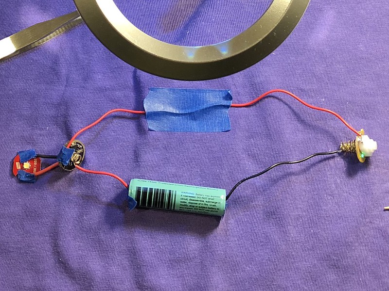
Here’s how I’ve done my testing to determine the proper bleeder resistor for a lighted switch. I also use a small 14500 protected battery just in case I accidentally short something. Left picture is where I’ve solder the wires to the LED and the driver, right is where I’ve just used tape to make the connections.

Hum, I didn’t try that, I’m honest! I was so tired of soldering and unsoldering that I put it apart and didn’t pick it up since Friday!
I may take a look into that scheme and make something similar.
But my guess is that something has already fried! But, nevertheless, the doubts can be clarified if that mount is done!
Thanks for the tip NeutralFan :+1: