Hi for the 20mm Buck Driver, (2S for 6v LED) can they be used for a tail clicky? (I see the drivers use Anduril, why I asked)
EDIT:
OK I went back through a bit and found this (answer to my question!)
To Lexel: best wishes hope you’re doing well!
Hi for the 20mm Buck Driver, (2S for 6v LED) can they be used for a tail clicky? (I see the drivers use Anduril, why I asked)
EDIT:
OK I went back through a bit and found this (answer to my question!)
To Lexel: best wishes hope you’re doing well!
Hello, i see that you have only 24 and 30 mm. I would like a 26mm is possible, other way i would ask a 24mm. I want to power 5x 26650 lithium in series and 4x sst40 led, for 5-6amp i think it is safe in proper mod.Can your driver do that? Is it constant regulated? Does it have any low mode? Thank you! If all ok send me total to pay you, thanks!
Lexel has been absent for more than 1 year. I would wait on his reply (soon).
I hope Lexel is OK ![]()
I don’t believe Lexel will be back.
Thats really sad…hope at least he is fine!any ideas where can i find what i want ? Thank you!
I only know of one place that makes buck drivers special order. Try here.
There are a couple of individuals in the forum, but I’m not sure what they can make.
Try contacting Quadruple.
Or loneoceans.
Every time I see this thread pop up I get a little excited and a little hopeful. I sure hope Lexel is doing ok. It’d be great to have him back in the forum even if he never soldered or sold another thing.
guys, thank you for your help, i don’t see anything fiting my needs, some solutions go over $60 with taxes, so better find something else, no need to go that high.
btw i found that:
do you think that this will work? I do have space to fit it, i am mostly concearned for cooling.
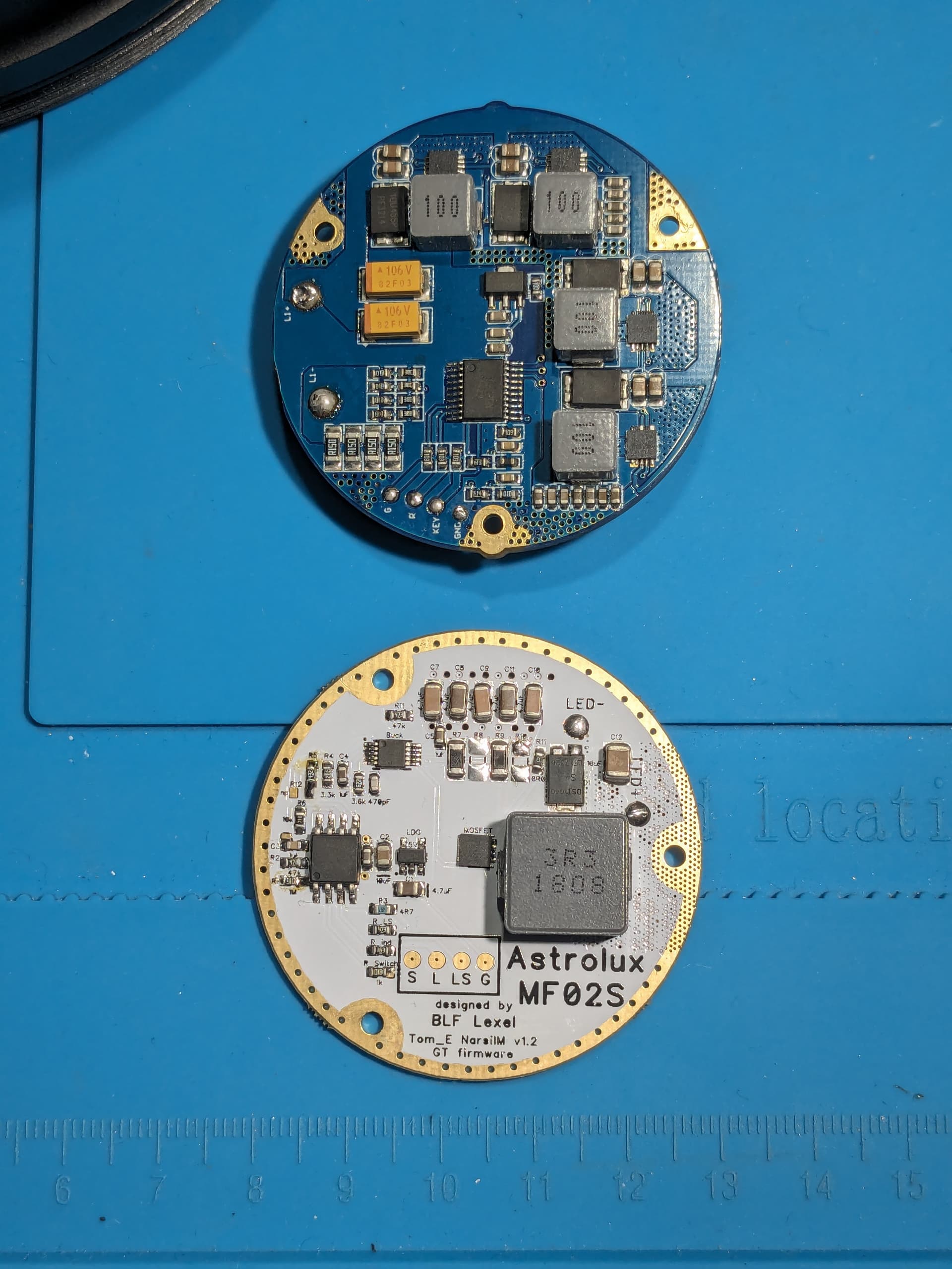
What’s the equivalent wiring for the Astrolux MF04S XHP70.2 and Lexel driver MF02S?
| Astrolux MF04S XHP70.2 driver pad | Lexel MF02S driver pad |
|---|---|
| L+ is LED positive | LED+ |
| L- is LED negative | LED- |
| G green wire to switch PCB | L Switch LED MCU controlled? |
| R red wire to switch PCB | LS permanent LED connected to battery? |
| KEY white wire to switch PCB | S Switch for UI ramping settings? |
| GND black wire to switch PCB | G common Ground? |
G and R might be the equivalent of:
L Switch LED MCU controlled
LS permanent LED connected to battery
Astrolux MF04S XHP70.2 has a driver with Mateminco 2017.9.6 REV: A03 printed on it. The pads are:
L+ is LED positive
L- is LED negative
G green wire to switch PCB
R red wire to switch PCB
KEY white wire to switch PCB
GND black wire to switch PCB
Here’s a photo for reference:
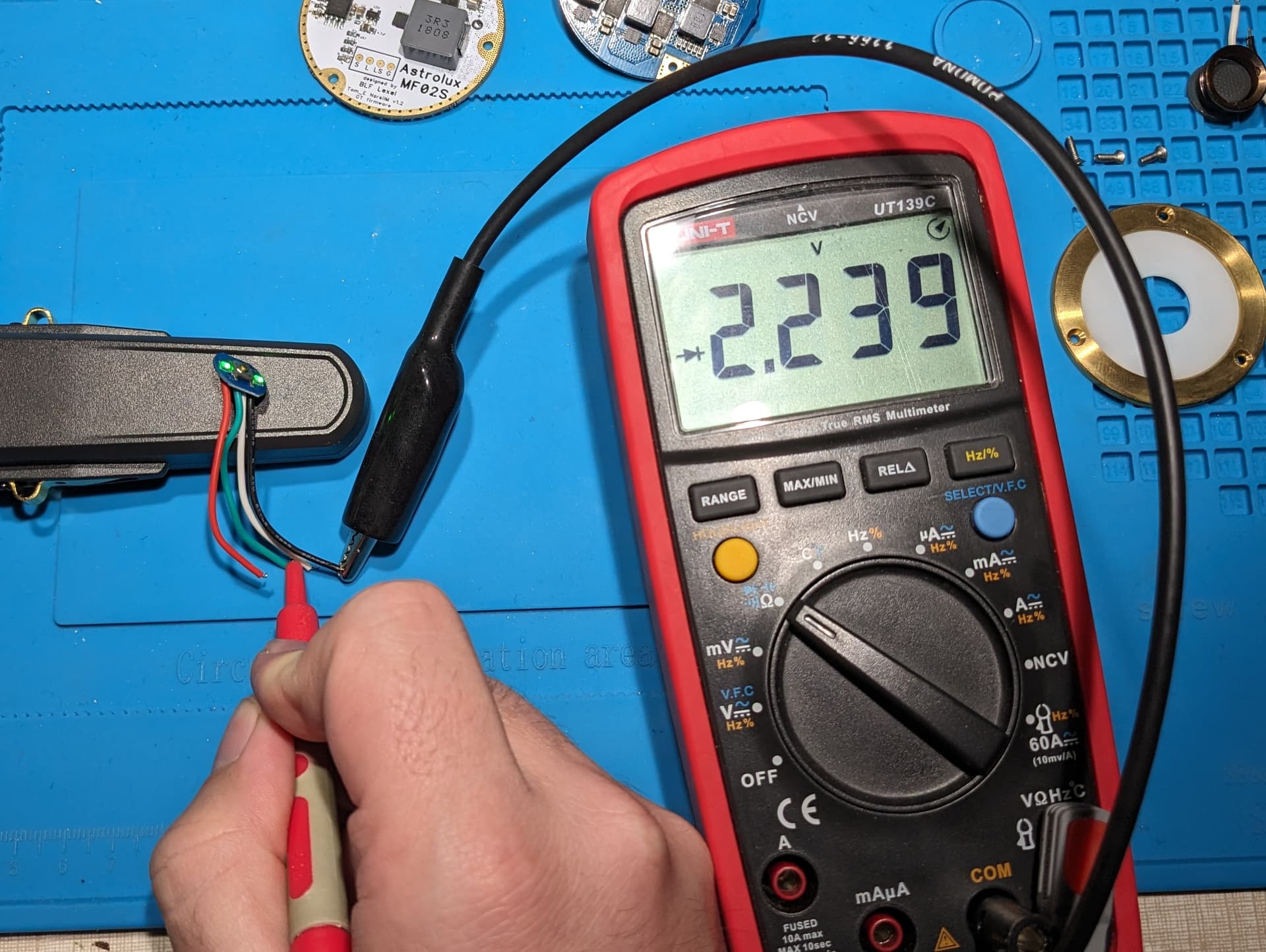
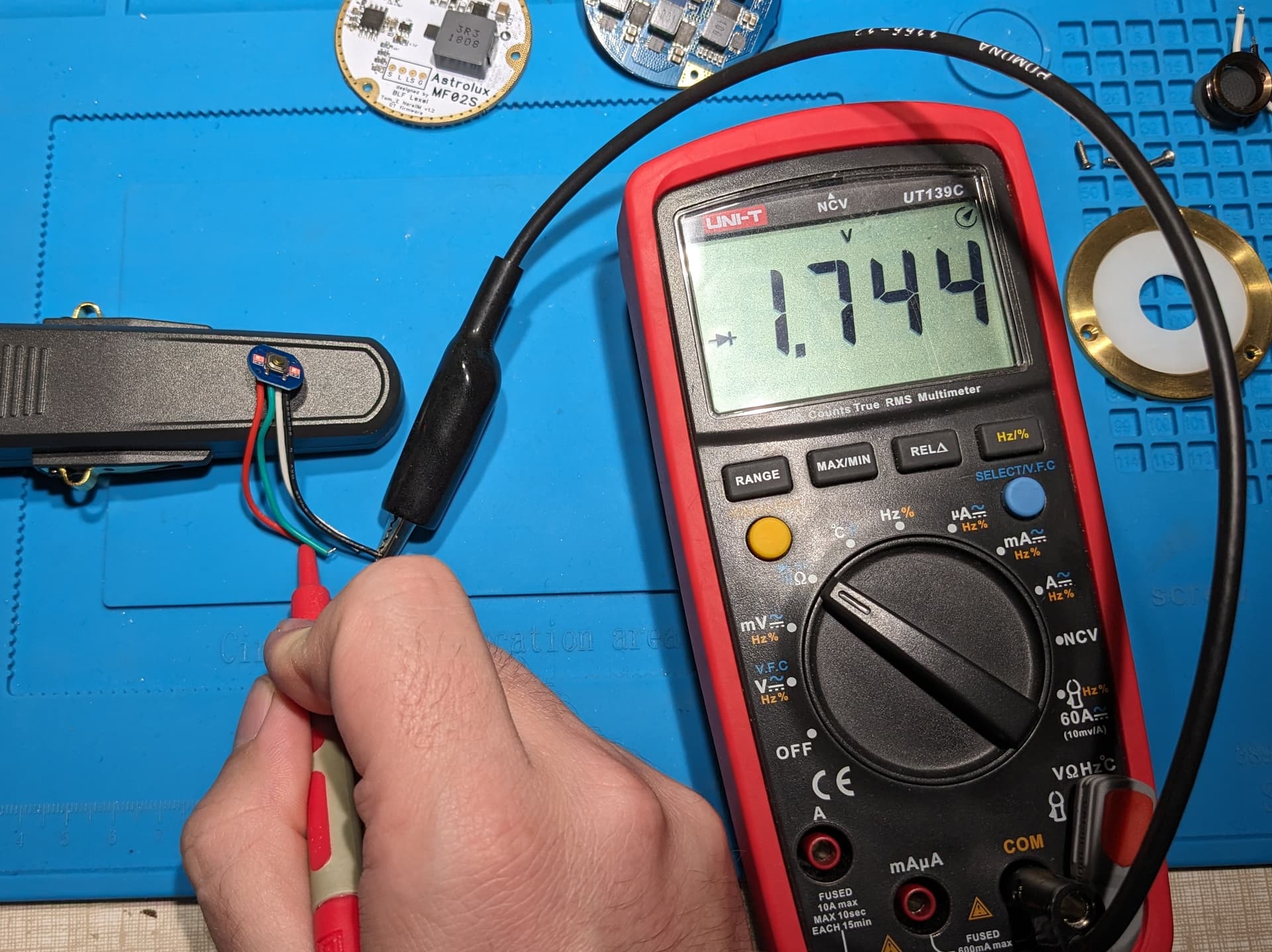
EDIT: I tested the switch PCB. I think the table above is correct.
Here’s the result:

The red and green lights are on. ![]()