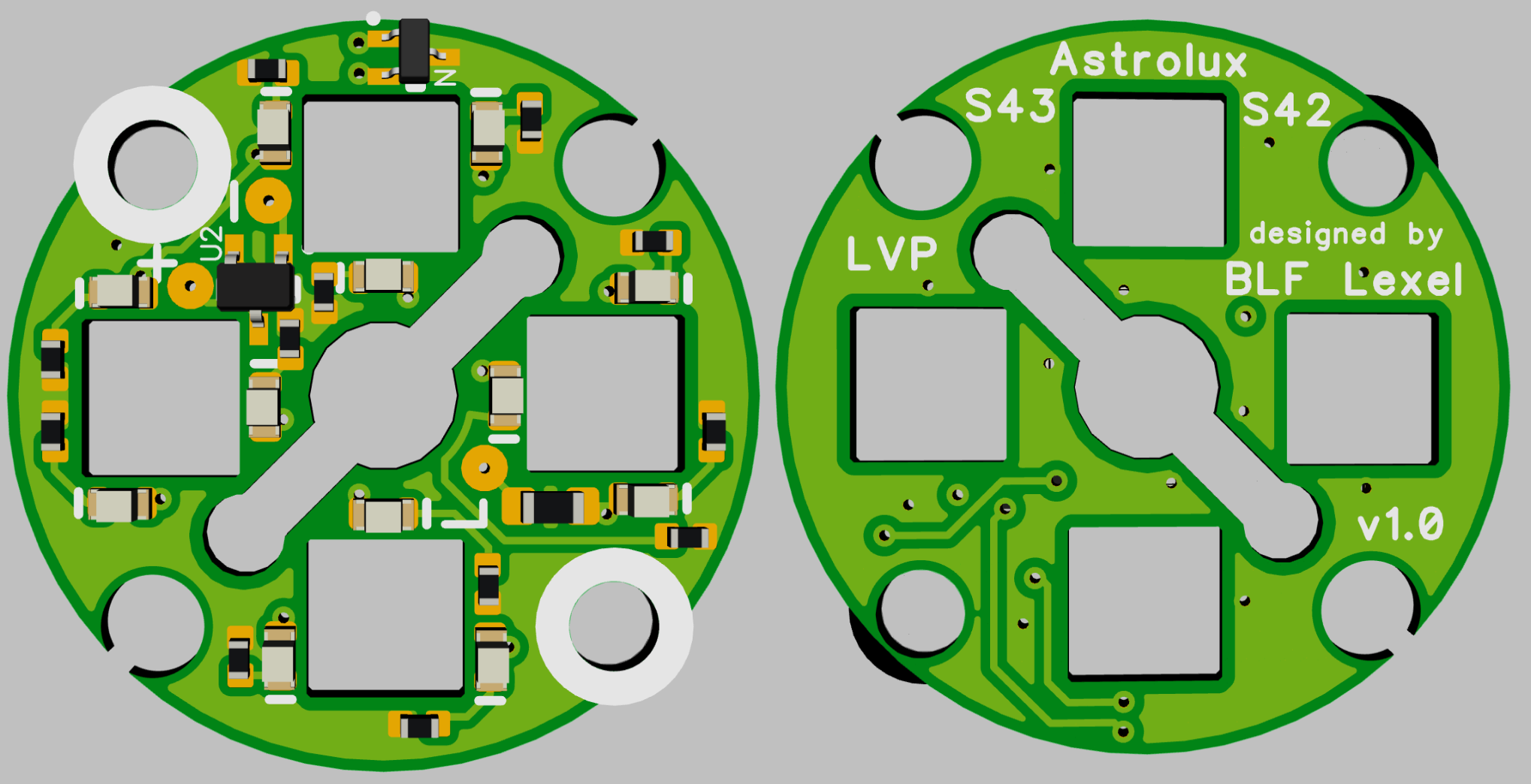
Astrolux S42 and S43 planned with LVP

Astrolux S42/S43 Aux board design drawn going in production soon
have changed to sort of hybrid pads 0606 tiny and 0402
uncut video in full lengh making an order from BLF member pogushe
He ordered one D4 Aux board for 5.7€ plus shipping

So I think I got to increase the prices as its even worse than on driver sales
I agree that the process is too time consuming for such a low price. Of course, if you’re doing multiple items, a lot of that time can be divided. But, even if you optimized it to the best possible, your price of 5.7€ is too low for such hand work.
Sad but I had to increase the prices, as they took a lot of work to build
I thought I may subsidy with some profit from drivers but calculating shows I am making still a loss
rev 3.1 is now available
one more full battery indicator outer LEds added, default is green but can be changed
LVP now shuts down the boards completely, LDO and voltage dividers ect. get cut from power, even if that drain is just 20-40uA depending which board
I had an idea how to get aux boards to the D18, it would need replacing the front cover
have all LEDs flipped so they shine through holes of the PCB, while all components are inside
I was reading about your FW3A AUX boards. Are they ready? I am still waiting for the SST-20 FW3A version. But the 5000K LH351D are already waiting here. And the new 10509 Optic is ordered from arrow and shoud arrive in 2 days.
I would love to get some of these aux boards in my hands as well! ![]()
![]()
Me too! I miss an indicator light on the FW3A, love the rest. This can fix that problem!
I’ll put my vote in for some FW3A boards too please
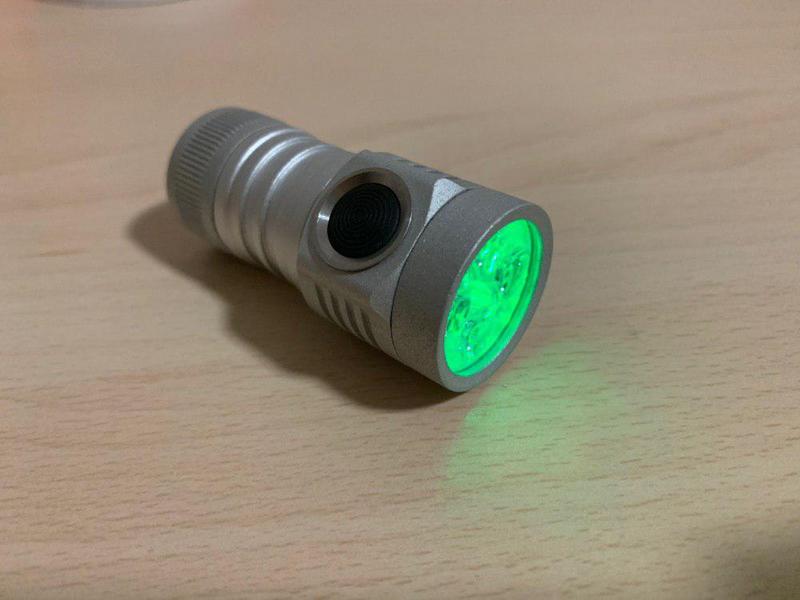
Finally got to work my D4 with full anduril and aux boards with high/low mode and LVP
Thanks to lexel for making the boards and helping me
Would the aux led PCB still fit if I did the 2S mod on the MF01 MCPCB? Meaning cutting some traces and connecting them to run on 6V.
If you use relative thin insulated wires like Teflon or thin silicone yes, I already did it with 0.35mm2 wires that gave less than 1mm dianeter
Isn’t that to thin for enough current? Can I also use thin copper strips or would that risk to short something?
Each 0.35mm² conducts only a portion of the current and is a lot more than the copper traces on the MCPCB used
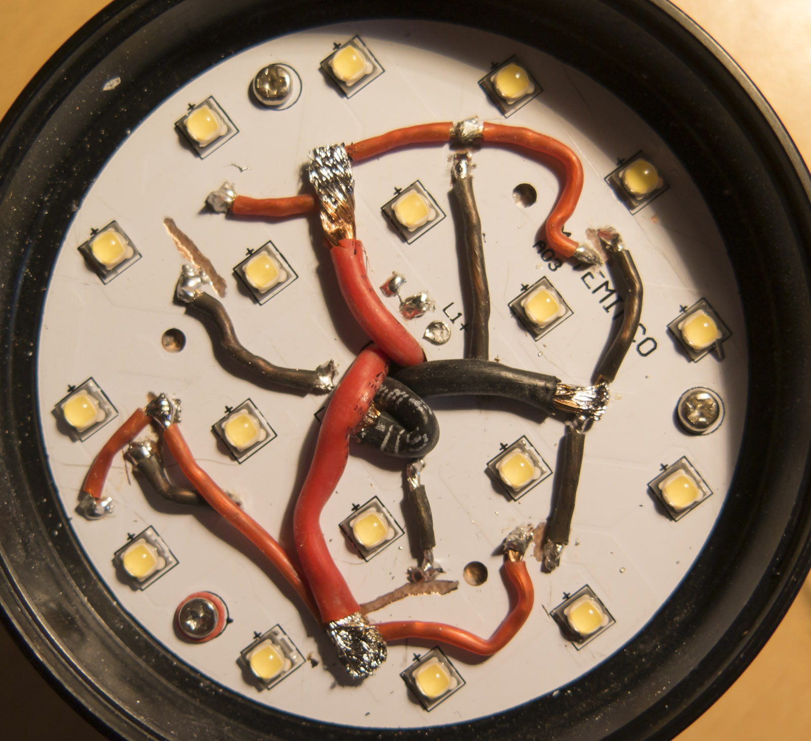
Connections:
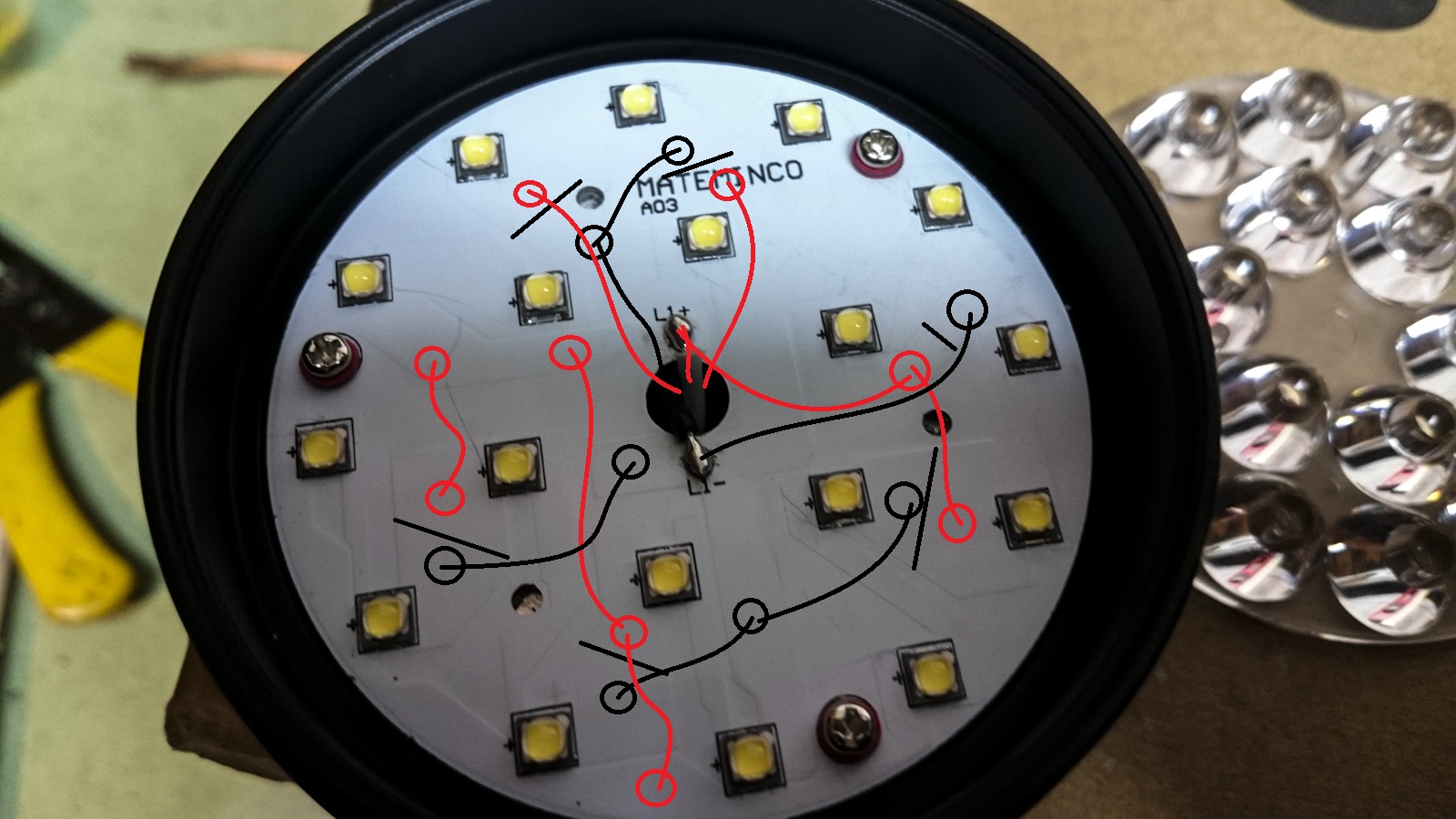
you have to avoid crossovers of them as well, you can try thicker but no guarantee it will fit
in this picture one red supply is not connected to the middle, that would need to go also to the center
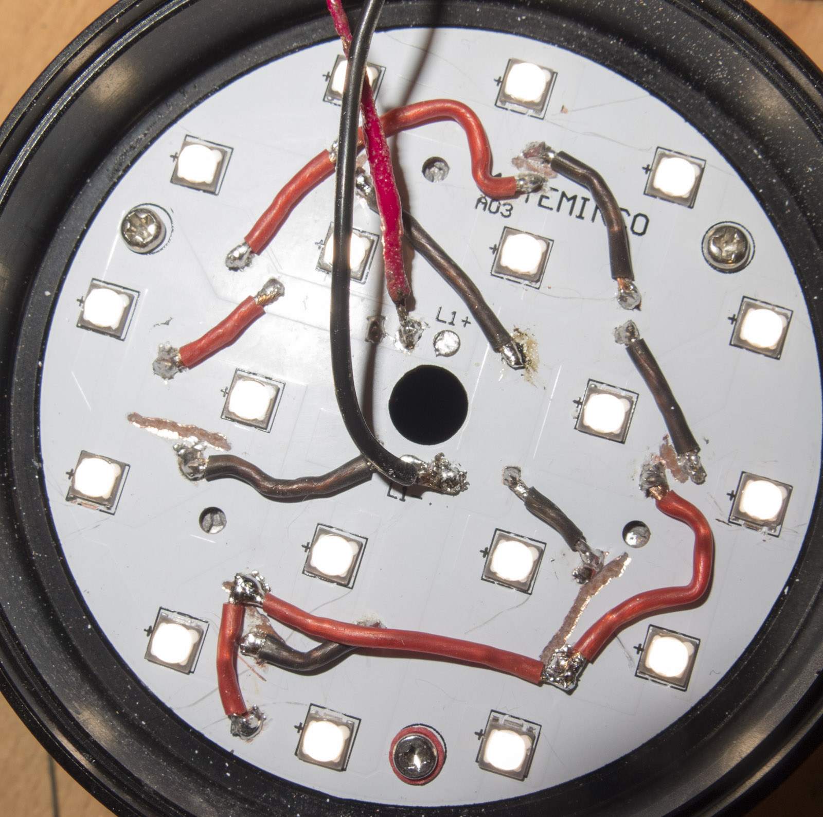
You can’t do an overkill like here
Thank you for the explanation, Lexel. I will see if I can get a new 2S MCPCB from Mateminco to make things easier. The aux board might fit better then.
I’m planning to convert a Convoy L6 to a MF01S… ![]()
I think a MCPCB is on BG for sale ridiculous expensive, its v2 6S so does not fit
I have here 1 2S/9P MCPCB stencil and emitters and 8 3S/6P (the only ones made before decision went to DD driver)
as I wrote I converted one from v2 to v3 with Aux board on top
does anyone (or lexel) have d4 instruction to remove the star or mcpcb so i can get to constant ground? I am trying to do a always on aux (already have in hand from lexel) with no firmware mod desired.
I’ve bridged the + and L with bare wire it sits just over the + from mcpcb, so that saves me one solder point. I just need to find the easiest location /way to get ground to aux board ground now.
I would suggest run the ground wire down to driver and attach at the ground point the switch uses. There may be other ground points on the driver (around edge), just verify it before attaching.
I’m not familiar with D4 driver layout. Are the main led wire holes big enough for a second skinny wire?
good point, it looks like i might have a very tight fit if I want to squeeze anything more through, and the very precise factory soldering might be difficult to put back. I just don’t know how to get to the back side (even if i could i can’t work with it unless i remove it). Can I simply drill holes through here to reach good grounding?
Dude, you have screws right there. They both thread down into the head and are grounded. Take your negative wire and strip the end about 3/8 and make a loop. Put the loop on top of that fiber washer on the top so the screw head squishes the wire. That will ground it out. If the wire strands are thin there should be no way they will get pushed through that washer. I suggest a loop so you get even pressure all the way around the screw head.