Nice collection of tips and tricks here. Thanks for the thread, and thanks to everyone for sharing!
11/11 sales —- any recommendations on a KSGER T12 setup from Ali or Bangood?
I found the ‘official KSGER’ store on AliExpress, but there are a lot of options that look very, very similar to each other.
Banggood had a lot of search hits too, but they all seemed to say v2.0 or v2.01 where the Ali options were v2.1s. I recall reading that the newer version was worth having, but I don’t recall why.
That’s very useful information, thanks. I’ve not caught up with this thread for a while, as I need to set aside plenty of time to take in all the infos that are presented here.
This is the station that I got, before knowing anything about soldering irons. It is supposed to come with three tips, but only one (pointed) tip was included, and I have never been able to figure out which tips are compatible. Since it was pretty cheap for such a big box I assume that it’s not regulated, and that there are probably soldering irons that will make it easier for me to find a way into this hobby, even though this one does have a hot air gun. The only thing that I’ve tried so far was to tin the ends of some speaker cables, but I soon found out that the tip I have is not exactly suitable for the job - a flat tip is probably far more useful.
Great info, thanks LEXEL. I have a fixed power soldering iron & realized it’s rather awful for any fine soldering work. That STM32 by Quicko looks great. Might get one, unless there’s a better deal somewhere else.
Looks the same as a 936 tip. Searh for 936 tip on ebay and you will find several.
Great info here thanks for posting! I’ve been considering a new iron for years and now it’s time.
I’m looking at these two, thinking I’d prefer the smaller #9501 handle:
<>
Could someone please recommend which T12 tip(s) would be best? Mainly for soldering wires to MCPCBs and driver boards and doing spring bypasses.
I’m not building drivers or soldering resistors or similar components, but if that requires a different tip I’d like to know about that too, just in case.
EDIT: I do plan to try some resistor mods
The stations I linked above already includes some tips:
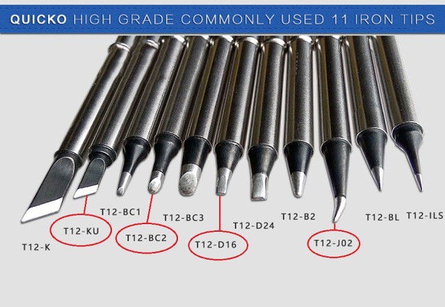
Quicko (set #4) includes 4 tips: J02, JLS, KU & BC1
KSGER includes one K tip
But here’s the whole selection I can choose from if I’d need something different:
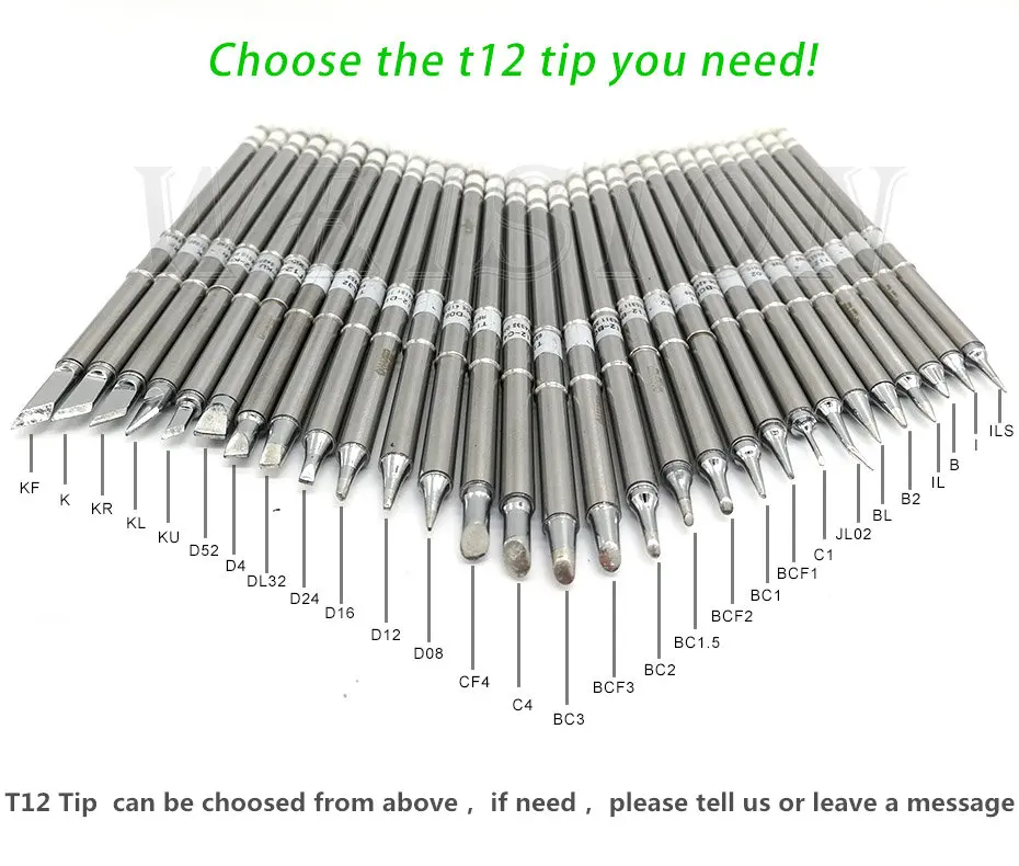
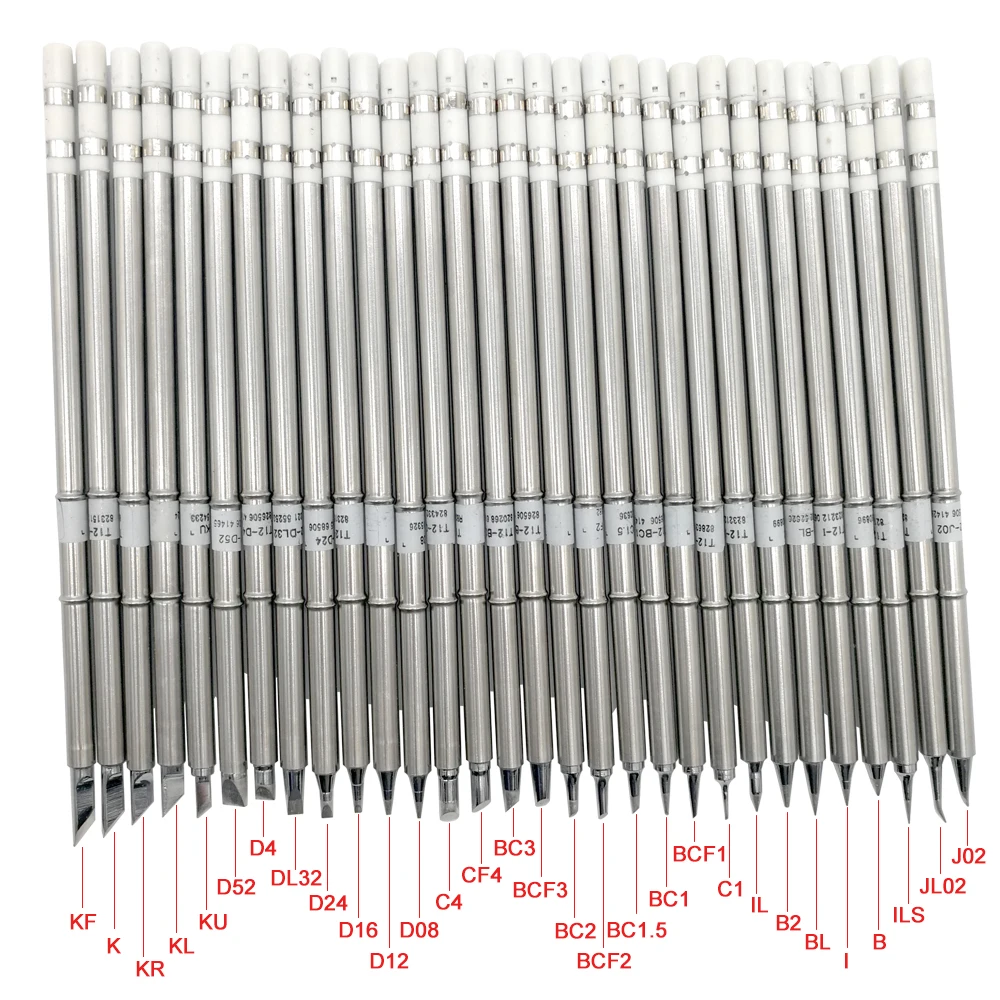
^ The ones that look good to me (circled in red) if I had to guess ![]() ^
^
I also found the Quicko (mini version) without built-in power supply for considerable less cost. I do have a dell laptop power supply that’s 20v 3.5a so I think it would work but I’d need to change out the plug-in tip.
There’s a plethora of different Quicko and KSGER units, (head spinning ![]() ) different models, different hardware and software versions…
) different models, different hardware and software versions…
Trying to find out the difference between Quicko T12-942 (STC OLED) and T12-943 (OLED-STM32)
There’s also the QUICKO STC T12-952 with built in power that appears different from the first one I linked in my post above.
I have full set of tips for my T12 and I mostly use B2 for everything and ILS for some really thin wires or SMD components.
Nice video, something I’m going to attempt on a tailswitch…… any tips for not shaking like a leaf ? ![]()
Hey beam0, my favorite tip is the D24 since it’s flat on both sides and can quickly heat up solder joints. For more precision soldering, the pointy tips are needed. The BC2 is nice to put a solder blob at the end of a spring for a bypass. I’ve never used the K tip that came with my 6 piece kit.
G0OSE, sometimes I’ll put some pieces of wood next to where I’m soldering to give my hands support. Also Helping Hands help a lot to hold the item you’re soldering in the position you need it.
I know this is kind of an old thread and I never commented on it earlier, but thought I’d throw out some suggestions that I use. I’m an electrical engineer and my sole income is with a partner where we sell custom test equipment to verify the integrity of electronic controlled valves (mostly in the oil & gas industry). My partner does the software and most of the building of the systems. I do the electrical design of the boards and I solder all of our own boards.
I use lead solder 60/40 or 63/37 (mostly Kester brand). I have two Weller soldering irons. One is an older WPCTP and the other is a newer WES51. Doesn’t matter the brand but they are fixed temperature of around 700 deg F and I have kind of fine tips on them. If you are doing a lot of soldering, you need to operate two soldering irons one in each hand to solder the SMD resistors and capacitors. It goes a lot faster with two irons plus its easier to center the part. First you put a dab of solder on each pad and then a drop or two of rosin flux. You place the SMD part on top or as near to the pads and then with the tips of the soldering irons, you melt the solder on both sides and when you let go the part centers itself automatically. It doesn’t take much practice to get good and fast at it.
I have no problem soldering surface mount IC’s with 0.05” pin spacing. I put some flux along the row of pads on the pcb and then hold the part with one hand with tweezers centering it, and then with one soldering iron in the other hand, just solder one pin to hold it in place. With the flux in place, the solder flows pretty fast as you sweep the soldering iron down the pins.
With IC’s that have pin spacing of 0.025”, I do the same and the trick is to use solder flux again. And I just sweep the iron across the pins and move as much solder to one end as possible. With the excess I dab it up with some solder wick making sure I don’t take off more solder than is necessary to eliminate solder bridge.
For the most part I avoid the IC’s that do not have exposed pins where you have to use something other than a traditional iron. I have heat flow soldered a number of LEDs but that is just a lot harder to do manually than when pins are involved.
I clean the boards with rubbing alcohol. I just use a small casserole glass dish and let the board soak for 15 minutes or so and then take a small nylon bristle brush to remove any undissolved flux. Then give the board a little rinse with clean alcohol, blow dry with the air compressor and then take a paper towel dabbed in rubbing alcohol to remove any streaks and make it look nice and clean. I place the dirty alcohol back in a 16oz bottle to use for the next time. When I pour out the dirty alcohol into the casserole dish to start with there is just a couple of tenths of an inch of alcohol at the bottom that is the most cloudy. I throw that out. So actually each 6”x5” board only uses up an ounce or less of alcohol.


Thanks, hiuintahs, that was a good post ![]()
Thanks for all the inputs, and the OP has a ton of great info I just needed to read it slower.
I decided to get the KSGER from US stock so I won’t have to wait so long, I’m getting the iron, one extra tip (D24) and a stand, costs a bit more for a useful tip because the irons in US stock only include one K tip, and the separate tips in US stock cost more.
For less cost I could have got a Quicko with up to 5 tips (my choice), but up to 30 days delivery time, which would be an issue if I’d get a dud and have to wait longer for a replacement.
Here’s what I’m ordering (US stocks):
KSGER T12 Soldering Station v2.1s
Soldering Iron Stand
D24 Tip
Plus I’m ordering some other tips from China.
Between the op’s and everyone else’s recommendations I decided on these 5 tips: D24 - BC2 - ILS - 4C - JL02
https://www.aliexpress.com/item/32906214146.html?spm=2114.12010615.8148356.2.5586174aHkNPnj
https://www.aliexpress.com/item/32966448895.html?spm=2114.12010615.8148356.12.1f0821devgwx5o
Here’s a link to the Quicko kits w/tips from China if anyone’s interested
I checked with the seller if you want different tips than shown send a note in the cart message.
Quicko T12 Station with tips
Banggood also has the T12 stations but not US stock, higher cost and can’t chose tips.
<>
About the handle: I’m getting the iron with the 9501 (blue plastic) handle because I felt it would be good to have a thinner grip and a shorter distance between your fingertip and the work, especially for fine or close work (and maybe better for shaky hands?) however after checking some measurements I’m wondering if there could be trouble with it reaching mcpcbs down the barrel of larger lights, although since it’s thin it should work just holding further back on the grip, but if it’s an issue I’ll order a longer handle, maybe the standard one, but I’m hoping I won’t need to.
Thank you Stefan,Very informative.
I just was curious about people raging about bad soldering wire from China, so I bought some cheap of it
SN63pb37 solder wire with unknown flux type
I wonder if its even possible to solder with this stuff not making >99% of the solder connections to be cold and cracked
I mean the fake Amtech flux they make is as good or even slightly better than the original
Just a short video first on my standard setting 285°C
I think I have magically forgotten how to solder using thgis stuff
not making any progress there, just a half solid solder stuff above the pad
then trying with usual recommended temp for 183°C tins
last good German solder Sn62Pb36Ag2
instantly forming a uniform blob of totally liquid metal that makes nice shiny blobs
alloying on the lower round pad didn’t look that great

Nice comparison video Lexel.
Wow! Thanks for that
**Forgive me if this is not the right place to post such topics **
I am replacing the PCB of my MyBooklive NAS Sata HDD which also requires copying the BIOS chip to the replacement board (the disk has a unique ID that encodes the chip).
The rescue of the old chip went smoothly and clean (picture attached - bottom).
The extraction of the chip from the replacement board damaged three pads (picture attached - top).
Pad 4 exists but its left side is in the air.
Pad 3 exists but the section on the left needs conductor exposure and soldering of the pad to the exposed conductor on the left.
Pad 8 was torn away completely (stuck to the replacement chip) and a pad construction is required after the conductor is exposed.
I have a hard time creating the solder and sticking of the solder to the contacts on the board.
Probably due to lack sufficient/quality equipment or lack of understanding of the correct process in such a repair.
Fixing the pads, if successful, is the first step. The second step is to solder the chip and will require extra professionalism so that all the 'construction' done at the first step will not collapse.
I would love to hear your opinions and get any advice or comment that might help in soldering the original chip to the replacement board and save the invaluable data I have on the drive.
Thanks for the comments.


You should take it to a place that fixes phones especially since you have important data on it.