Interesting stuff that I never wondered but now do want to know :-), thanks for the testing! So even HKJ’s fancy power supplies can not supply a constant voltage as well as a battery. Buck and boost driver also have inductance in the circuitry, would PWM on those that also suffer from this effect? It would be nice to have some scope images to illustrate what is happening here (but perhaps hooking up a scope would even influence the inductance in the circuit).
Not when the load changes 1000 of times a second. I usually have a capacitor fairly close to the switcher in these tests, but my test leads add some inductance. Batteries are really good at handling these fast changes.
EasyB, thanks for letting me know about your test.
I might have guessed there could be an issue with a switching power supply, but I did my test with a variable linear supply (I think - heavy transformer inside), which I understood to be have very clean, ripple free output. I guess I could see the fast switching of the load being a problem for the supply, however.
This would explain why HKJ and I both saw poor regulation of a QLite on PWM modes, but Zeroair saw very good regulation on another Qlite in his Okluma. I had concluded it must be poorer quality 7135 chips being used that don’t react quickly enough for a high frequency PWM.
I will have to look for some time in the future to repeat my test with battery to verify I get the same result as your test.
Thank you EasyB, that’s really useful to know.
i might have missed it but what is the blue trace measurement?
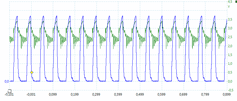
It is a photo diode place in front of the led, i.e. it measures the brightness, but is uncalibrated (That is the reason for no scale).
Thank you, that is very clever.