I didn’t realize DMMs can do that. In fact, I think mine can!
Honestly, I didn’t really realize either until about a month ago. “I wonder what this one is for…? Ohh!” ![]()
Yeah, it’s pretty easy to measure PWM speed with a DMM if it has a frequency function. Take the head of a light, like a Convoy S2+ or similar, with a normal LED and reflector inside, but no driver. Run wires from LED+ and LED- out the back end. Connect a DMM to it, and you now have a light-sensing device.
After that, basically just turn it on and point another flashlight at it.
This works because LEDs don’t just convert electrons into photons. They can also run in reverse, converting photons into electrons. They’re not very efficient in reverse, but it’s good enough for measuring PWM.
I think I have a light sensor from an old Arduino kit somewhere, but this sounds more fun.
I tried a couple of photoresistors, actually… including one which typically comes with Arduino kits. They’re less convenient to use. It’s because they don’t actually generate voltage like LEDs do; they’re just photosensitive resistors. So they need to be powered before they can meaningfully be measured. Can’t just connect a DMM to it and expect it to work.
The LED method is the simplest I’ve found… and many of us already have the parts laying around.
Also, since it’s so easy to sense light this way, it’s really easy to add a light sensor to flashlights. They already have a brain and an eye; all we have to do is connect the two. So add a trace or a wire from LED- to an ADC-capable MCU pin. It acts as an “optic nerve”.
The FW3A has something like this onboard. The only difference there is it has a filter in the middle of the optic nerve, to center and highpass the signal. So, it centers itself at 0V over time, and spikes up or down when the light level changes. Basically it only sees edges.
Should anyone want to go the technical path of using an oscilloscope to measure flashlight PWM, this was my first review to BLF.
An expensive solar cell like this one that I picked up from Amazon? for about $3 will work with a DMM that can measure frequency to get a handle on PWM without the need to make an electrical connection to the light.

But there is more to it than just the frequency. It also make a difference what period the light is on during the cycle.
Take a look at these 2 O-Scope pics. The first is a lamp on high that has PWM that can be seen on the scope and on video as it steps on the frame rate. I passes the finger wave test and I can’t see it. The horizontal scale is 2ms.
PWM High

PWM Low
The second shot is the same light on low. Same frequency but the light is on for less of the cycle. This is clearly visible to the finger test.
Terry’s post goes into great depth on getting a measurement of PWM.
If I’m interpreting it correctly, that light uses PWM at about 2.5 kHz?
I have an old iTP A3 EOS which pulses at 2.45 kHz or 2.42 kHz depending on the mode. I had thought the pulsing was visibly obvious until I showed it to other people, and they couldn’t see it. It’s weird how different people’s perception is for this sort of thing.
Looking at the oscilloscope though, I mostly just want to draw on it with sound waves. People have done some cool stuff with sound.
")
Terry’s post best post. 5/5 stars, would read again. ![]()
Each full black line on the scope is 2ms.
If I’m doing the math right (which is a doubtful thing at best), I see a cycle taking 4ms and that equates to 250Hz.
You can easily see this PWM by waving fingers.
Once upon a time this came easily to me, but that was long ago.
Now I used this Web base converter:
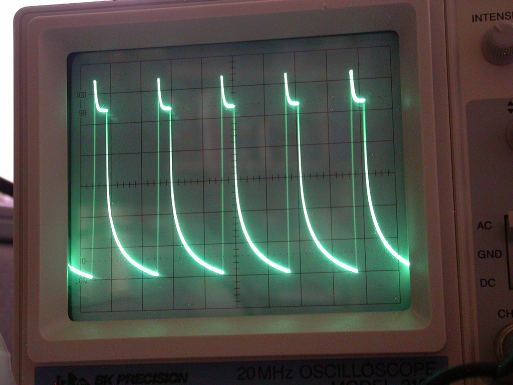
Here is a pic of the worst PWM I’ve seen so far, about 10ms peak to peak = 100Hz

This is full on seizure mode. Pare of the problem is the light is on for so short a time in the cycle period.
What kind of camera were you using? If it was a rolling shutter that would explain why both images show dashed lines with the larger droplets but not smaller droplets. It’d be like the effect you see when looking at a plane’s prop through a cellphone camera.
I think I’m going to try this at home.
Oh, okay. I was reading it as 2 ms for the entire display, not 2 ms per grid square. So, yeah, that’s very slow PWM. ![]()
Nope, no rolling shutter. I avoid those. Everything in the pictures was a single moment in time.
The larger dotted lines were caused by water droplets changing shape, not by camera artifacts. That’s one of the main reasons I don’t recommend the shower test — even if the light doesn’t pulse, the water droplets kinda do. And it can be hard to tell which is which.
Sounds like a terrible testing method then! I wonder if there’s a good way to positively identify PWM that doesn’t involve a shower or high end equipment… maybe a homemade Phenakistiscope? Would just need to get a frequency that’s some multiple of the PWM and it’d flicker more distinctly, I think.
Both PWM and CC can produce visible flicker and can produce dots in falling water, and dots when waving the light.
And both can produce distortion in a video or photo.
The question is not whether a light has PWM or CC, the question is whether the flicker is visible to the naked eye.
Waving a white index card through the beam works well. For fast PWM it requires waving the card quickly though.
Quickly waving a light usually makes bad PWM very obvious to me.
I can also see it by moving my eyes instead.
Early LED tail lights and cheap LED holiday lights drive me crazy. ![]()
I was thinking (never a good sign) about this PWM frequency stuff and how to get a look at it without having to use a DMM with a frequency function or a scope.
Several methods have been put forward about converting photons into volts, most of which cost almost nothing other than some tinkering. What’s needed some way to convert that output into something useful. Something free maybe, as we are the BLF…
Since most PWM switching takes place in the audio ranges, why not try some audio analyzer software?
RoomEQ Wizard is free multi-platform audio analysis software widely used by audio junkies to measure acoustic properties of rooms and loudspeakers. It’s lots of fun to play with and there are plenty of videos and forums on how to use it. Find it here:
Instead of a microphone as an input, use the output of whatever you can cobble together to convert light to volts. Then use the real time spectrum analyzer to look at the frequency of the signal. There should be a sharp peak at the PWM frequency. I would expect to see harmonics from the square wave or other noise, but I think this would work.
The only got’ya would be matching the voltage output of your source with the input of the computers sound card. Most audio line voltage is in the 1ish volt range. Microphones run lots lower, but I’m not sure what the computers inputs can handle.
REW (nickname for the software) can also act as a signal generator. One could run the output of the sound card through a simple switching transistor or a small amp to provide the correct voltage to drive an LED. Then you have an infinatly adjustable (well 10Hz to 15K-20KHz depending your sound card) to experiment with PWM.
You could even hookup a speaker to your photocell and put the speaker next to the computers microphone to get a signal in that way.
I’ll see if I can do this sometime and report back.
All the Best,
Jeff
Jeff, I’m looking forward to seeing the results you get. IIRC, there has been some experimenting with using a sound card like this in the past on BLF. A quick search would probably pull up an old post or two about it. I think there are even apps designed for it, or there used to be. Or maybe I’m remembering wrongly.
It works. I’ve used a guitar tuner app (PitchLab) and a mic to measure PWM. It works particularly on medium-to-high modes when pointed at black fabric with very small fibers, thanks to the photoacoustic effect.
The hard part is getting the signal into the app. It either needs to be amplified enough to be heard by a microphone, or it needs to be otherwise routed in more directly.
Selfbuilt on CPF used a sound card frequency analyzer to measure PWM in his reviews. He made one of the largest and most respected collections of flashlight reviews ever created.
However, even that can’t detect anything faster than the Nyquist rate, or about 22 kHz on most devices. And even below that, there’s typically still a lot of aliasing until at least one octave lower, or ~11 kHz. When reviewing a BLF light with fast PWM, he claimed it had no PWM, just “noise” of some sort in the signal.
So as soon as I got a DMM with the right features, I switched to the LED-as-sensor method.
Well, most sound cards now can do at least 48khz and there are sound cards capable of 192khz for professional use. They don’t look or act like what most people think of “sound cards” but still… ![]()