The protection circuit is easily removed from the cell that comes with the TC20. Just grab it on the edges of the circuit board itself with some pliers and pull upward while putting pressure to one side , kind of an angle and the circuit board will pop right up. Then sand the little sharp edges smooth and the cell works fine in the light.
I do suggest if you do this be sure to have an extra battery wrap handy and an insulator . as the whole positive end is exposed after you do this , so the negative part is also exposed on the same end and a possible short is likely if not properly insulated.
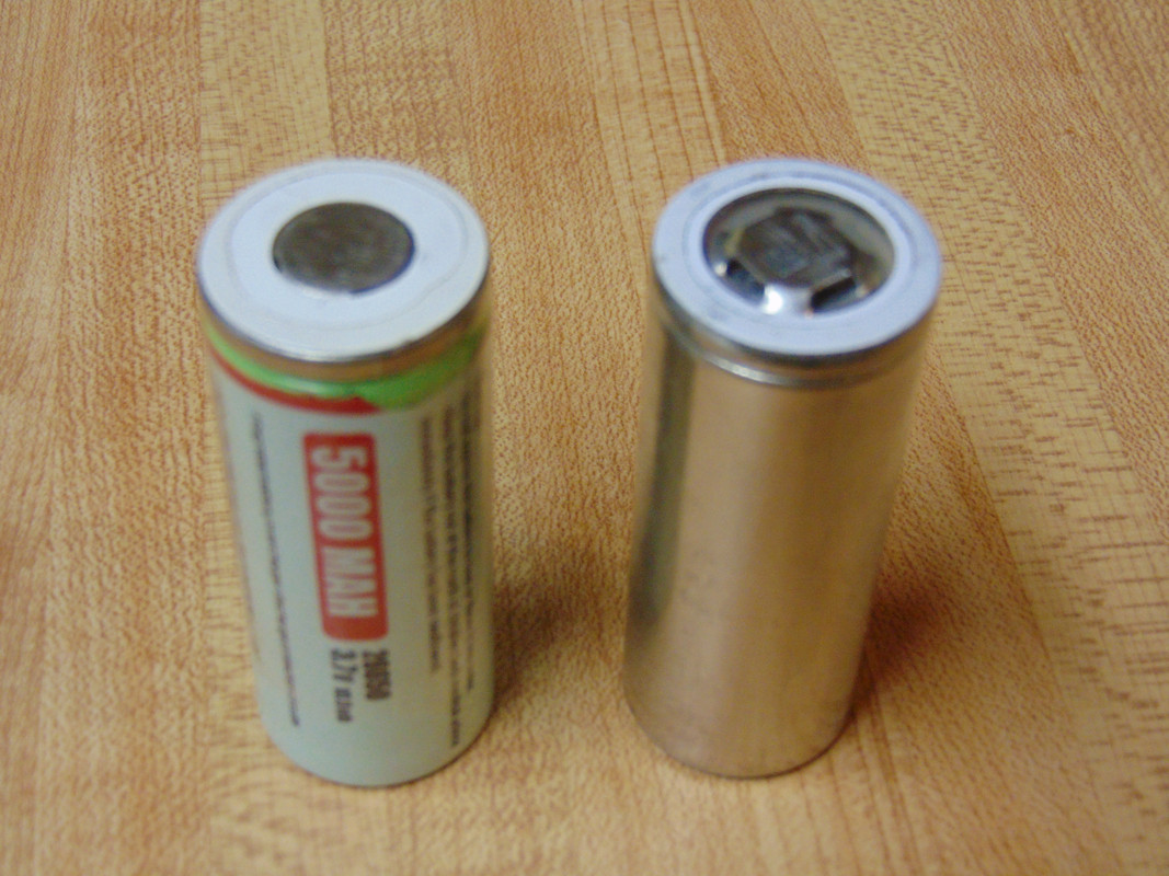
Here are the cells from my V6 and the TC20 both that I took the circuits off of and both work fine without solder blobs or anything.
Well, not exactly 6V, more like 6.3 or so, it will vary as the driver tries to keep up with the thermal demands on the emitter and such. Changing the load on the driver may well end up with different results (different requirements from the new emitters)
I think SKV89 asked about 6V or 12V and not about exact values. I changed the emitter on MT-G2 myself and checked it from this angle. It is known that the exact voltage value will depend on the emitter parameters.