Oh ok then. Now I get why there were no AR lens for the Q8. Too much bad tint shift.
Those are really nice, and I miss the one I used to have, but nixie tubes are expensive… especially if I want a proper ‘5’ which isn’t just an upside-down ‘2’.
However, I’ve been tempted to get some nixie-like 16-segment VFD tubes, and connect it over USB for use as a general purpose 8-character display. I haven’t found any kits for that though; the closest was a clock which doesn’t talk to the USB host at all.
My Q8 had AR coating. I scrubbed it off, but it took a few hours with a polishing cloth. Tint was much better afterward.
Here’s a shot from halfway through that process. It was reflecting a big yellow light source, so the yellow parts were clean while the rest was still coated.

Yes it was, I have bought eight in total only three has the green tint.
I have four more on the way I just hope they are the real ones.
Thanks to Texas_Ace
my Utorch S1 Mini NW LED:

Now has an N219b 4500k 9080

fwiw, lumens dropped by 50% and the light now runs noticeably hotter (dont have any IR temp data before and after, but I speculate its twice as hot, inverse of the lumen reduction)
neither the piss yellow of the XPL, nor the excess violet of the N219b are noticeable “in actual use”. The differences are only obvious when comparing different beams side by side.
This is seriously functional art! I love it!!!
I modded a Sofirn SF10 with a BLF A6 driver and a XP-L in 5A. I also tried baking the light and I like how it turned out.

I worked on a triple SST-40 build using an F13 for a host, and a reflector I got from Kaidomain.
I’m going to mount the emitters on some 11mm sinkpads. It took me a while to figure out how to keep the MCPCBs in the right positions while I soldered them down to a copper disc.
I ended up printing a template on some index card stock, and then sticking the top surface of the sinkpads to it with non-corrosive silicone adhesive. Once it set up, I trimmed away most of the paper so I could work around the perimeters with a soldering iron.
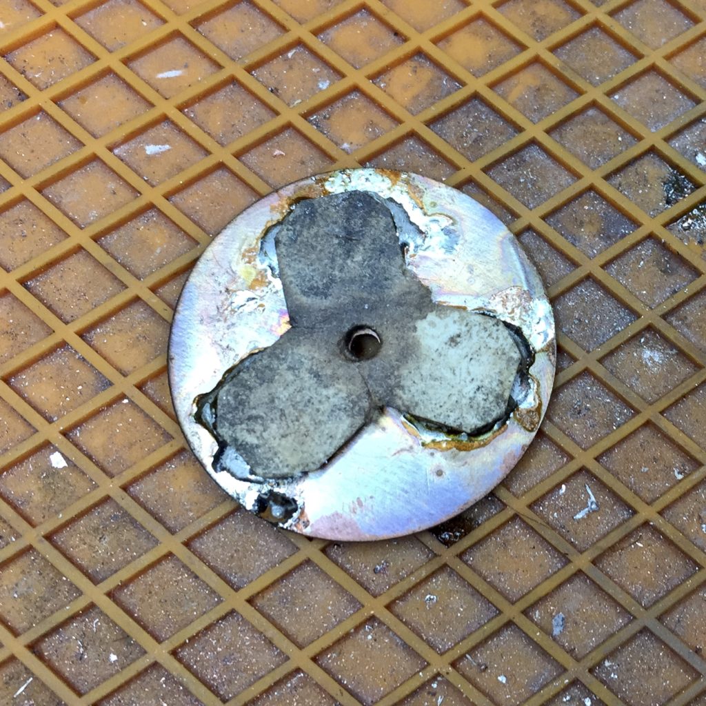
The paper charred a bit, but it still did its job.
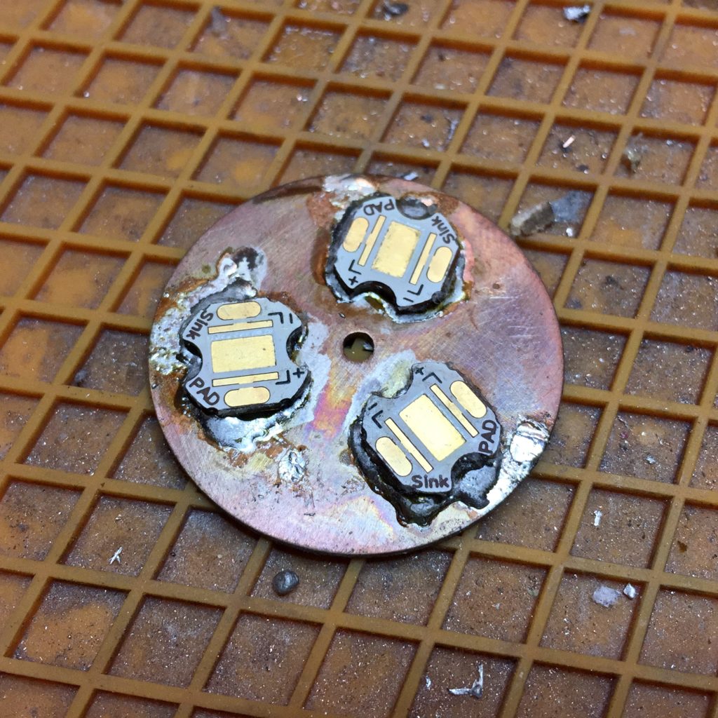
I peeled the paper and adhesive off with tweezers and then rubbed any residue off with a cloth.
Unfortunately, the positioning was off. I may have made a mistake when measuring the reflector and/or didn’t get things lined up quite right on the template. I put some fresh flux on the solder, heated the assembly up, and nudged the MCPCBs. I checked with the reflector and the reworked alignment was much improved, so I cooled it down and cleaned it up.
Now I have to figure out how to do the electrical hookups without interfering with the reflector, ideally without having to buy something and wait for it to be delivered.
^ proper modding, and getting the ledwires right together with keeping the centering pieces will be a major challenge ahead!
Cool TK! I’ve been thinking about getting my boy a clock like that for his room… might be pretty neat to build it myself! ![]()
Did you individually solder every pad or use a hot air station? ![]()
I tried hot air first, but found it didn’t work. These particular LEDs melt before the solder does. So, fine-tip iron instead. Tin one pad, flow the LED onto that and let it cool (to get the placement right), then very quickly melt some solder onto the other five pads. Except more efficient, so… tin 105 pads, flow 105 LEDs on, then connect the other 525 pads. Then check all 630 connections with a small tickle of power, and fix any bad connections.
They’re some sort of small COB-like setup with three individual emitters under the phosphor layer, and a very easily-melted plastic case. Not a type I’ve used before, and not the level of quality I’m used to. And it’s two columns too narrow to do 24-hour time without the digits touching the colon. But it works. And it’s pink. And it seems to keep pretty good time.
Hot air didn’t work well on the other one either, the 7-segment style clock, since the parts are small enough that they just blow away as soon as the solder melts. And it has a much less accurate clock chip so it gains 3-4 seconds per day. But it used more familiar parts, and fewer of them, which helped.
Thanks for the detailed response, think I’ll just get him a Cuckoo clock instead…
After my first attempt with the XM-L2 T3 7A3 CRI90 in the Q8, I had so high hope for, but turned to be a complete fail.
I when ahead to try something I knew I wouldn’t like, sliced and lightly polished SST-40’s :

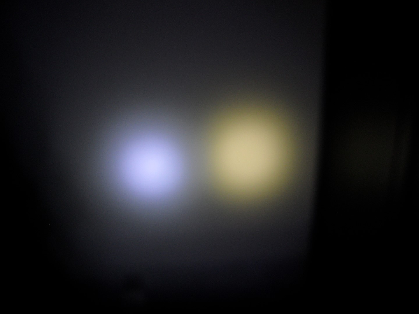
Q8 SST-40 (left) Q8 original (right)
The SST-40 appear a bit more blue in the image, and the XP-L HD a bit more green, the hot spot of the SST-40 is more defined than the XP-L HD, I like the beam profile of the SST-40 but the tint is much to cool for me.
I don’t know the lumen output or the amp draw but it gets very hot fast. I have considered DD the SST-40’s, but I think it will give them a green hue.
It looks like they have a new one arriving in a couple weeks. It seems to be easier to build and has more pixels and features, so I might do that one too. The display is five pre-built 5x7 matrices with through-hole connections, for 25x7 pixels total. I don’t know how this stuff got started, but it seems they’ve got “maker” enthusiasts for clocks too, not just flashlights.
No open-source code though. ![]() It’s too bad, because I’d love to modify some things. In particular, it’d be cool to make it act as a USB serial device, and display whatever data it received from a computer. At 19200 baud and 25 7-bit characters per frame, it should be able to do a bit over 80 frames per second.
It’s too bad, because I’d love to modify some things. In particular, it’d be cool to make it act as a USB serial device, and display whatever data it received from a computer. At 19200 baud and 25 7-bit characters per frame, it should be able to do a bit over 80 frames per second.
Not really concerned about the number of solder points, can’t be a lot different than building 25 FET drivers at a time and I’ve survived that… ![]()
I guess everyone knows I have a thing for the X6 format flashlight. I have some 12 of them, all done different in some way or another. Well today I added yet another… this one is an emitter I’ve never tried in the X6 before, the massive Luminus SST-90! ![]() I pulled off the dome revealing the metal frame around the die and it’s filling of silicone. Luminus puts a sort of tacky silicone over the die, then caps it off with the harder dome, so when popping the dome on the big 90 this layer of protection remains in place. It can be taken further, but for now I’m leaving it there to see how it works out.
I pulled off the dome revealing the metal frame around the die and it’s filling of silicone. Luminus puts a sort of tacky silicone over the die, then caps it off with the harder dome, so when popping the dome on the big 90 this layer of protection remains in place. It can be taken further, but for now I’m leaving it there to see how it works out.
I built an FET driver with 5 modes (not as easy as it might sound, I had to load a new boot of Win 7 the other day and it took me over an hour to re-install all the appropriate software and such just to flash the driver. ) UGH! Finally got it thought, and an initial read has it making right at 2000 lumens on a rested and partially discharged cell.
I mounted this SST-90 on an 26mm MaxToch MCPCB intended for the slightly smaller MT-G2 emitter. To get this in the X6, I had to open the emitter shelf on the lathe first. Also had to open the reflector opening and use Kapton tape to ensure no short circuit. So far so good! ![]()
Edit: Looks like the Sony VTC5A fresh charged gives maximum yield, 2504.7 lumens at start… Works for me!
Edit II: It’s pulling 20A at the tail from the VTC5A, no longer fresh. And with the excess silicone removed from around the die, it’s making 2553 lumens.
I should also add that the central or hot spot region of the beam is fugly! Egg yolk yellow in the center, the rest of the beam looks nice, white.
Who doesn’t? ![]()
It’s a good design. The BLF one in particular, with its threaded-in reflector, works really well. I like it a lot more than the C8 host design.
TBH though, usually I go for a D1 shorty instead. It’s almost as throwy as an X6 but small enough to toss in my purse and forget until I need it.
I have 13 X6 flashlights now, every one sporting a different set-up and power level. I guess the most “normal” one is the SST-40 variant. ![]()
I spring bypassed the tail switch and this one is now making a whopping 2804.85 lumens in Turbo, level 5 of 5. ![]() I think that’s the single highest reading I’ve ever seen on a 3V emitter. Highest current draw from a single 3V emitter as well!!
I think that’s the single highest reading I’ve ever seen on a 3V emitter. Highest current draw from a single 3V emitter as well!!
Level 1 is good for 27.6 lumens
Level 2 is good for 138 lumens
Level 3 is good for 1041.9 lumens
Level 4 is good for 2001 lumens
Level 5 is good for 2804.85 lumens (Edit: Correction, fresh off the charger the VTC5A yields 2998.05 lumens through the SST-90)
This SST-40 makes some serious heat! And pulls down the cell exceedingly fast! Just taking those readings on the light box dropped a fresh cell from 4.20V to 4.12V, on time of mere seconds.
And FWIW TK, this one is the Kronos BLF light, with the screw in reflector. I don’t like these as much as the original Eagle Eye because they’re not made as well… the original has a true Type III ano and is just made better, more refined, all around.
I have a chopped X5 that takes a 14250 cell, it’s cute! Pocketable but with throw, even if the cell doesn’t have enough capacity to warrant it. Perhaps I should chop an X6 for use with an 18350… ![]()
Edit: This is a VERY large single die emitter! When you have to scrape masking off the contact pads of an MT-G2 MCPCB to allow full placement of the SST-90, you KNOW it’s huge!

So, in a move totally unlike myself I pulled the 18Ga leads in favor of 20Ga in order to tone this one down some. It’s now making 2853 lumens so it didn’t actually take it down much, but it just seemed too over the top, even for me. Must be getting old…
(even with 20 ga leads it gets too hot to hold onto in about 12 seconds, lot of current being drawn here!)
You are right.
Instead of putting 18AWG wire, you should be putting dual 18AWG wires for even more power!
Maybe 3500 lumens is possible? Or maybe you could build a custom tube with copper rods and a Samsung 30T for maximum power.