Sounds like a good point. I don’t know what the “multiply” you mentioned is (link for my benefit?), but I’ve been assuming that a 2D array might be unnecessarily costly.
I’ve been eyeballing the 2D array mostly for formatting purposes in the code (easier to edit the modes), but I suppose you could format four 1D arrays in the a similar way. I guess the other advantage of a 2D array is that you might not be able to compile if you mess up the array? EG with the 1D arrays you could add a mode to one array and not to the other… what does an array return for an out of range index? I guess whatever is present in that memory area. Not really a big deal though.
Oh, the multiply thing depends on whether the compiler can figure out how to optimize it out. But if not, saying “foo = values[bar][quux]” translates into “foo = *(values + ((quux*array_width) + bar))”. Not an issue on full-featured processors, but on minimal MCUs it’s smaller and faster to split each row into its own array and do “foo = values_quux[bar]” when possible.
If quux is a literal constant though, and the array size is hardcoded, the compiler should be able to figure out how to optimize the multiply out and use a constant instead.
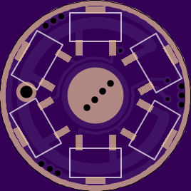
I’ve continued to barge forward with the existing configuration (1+2+3+FET with PWM on 1 & the FET). Clearly there has been a minor overhaul to the layout. Here is what it achieves:
All small components have been labeled, correctly I hope. D1 just got a little triangle
All non-GND pads are a minimum of 1mm away from the outside edge!
All physical component outlines are a minimum of 1mm away from the outside edge!
Zener footprint added. (optional)
Note that there is interference between outlines and bare copper, so finished boards may look different.
Wight, it looks like you’re not using a GND poly but instead trying to trace out GND airwires?
It’s a better practice to skip over ALL GND airwires, just draw a big poly around everything and let eagle take care of it all as the final step. This also eliminates you having to manually put a GND ring in copper (just draw it in tstop). I do notice you have a couple poly’s already on the board (atleast I hope those shape’s are poly’s and not just a bunch of lines drawn together), you’ll need to assign them a lower rank (higher number) so your GND poly can be ranked as top priority (number 1).
If this doesn’t make sense let me know and I’ll shoot you over a sample .brd to look at. It also makes the boards just look better in general. Don’t forget to turn off thermal’s on the top, you don’t want them on the FET’s GND.
I stopped doing that for some reason. Can’t remember why though. The pours you see are poly’s.
Now that you’ve brought it up I’ll take another look a it on the next edit. Thanks for mentioning it.
I think that for my workflow leaving GND traces for the last step is a definite no-no. OTOH I might start using a GND poly to wrap a completed driver up in a nice looking way. The problem remains that any major refactor of the driver would require removing the poly and droping a bunch of GND traces again so that I can think correctly. It’s easier for me to paint myself into a corner when I’ve got a lot of airwires…
I had this issue too at first but I’ve actually found it easier to do not tracing them now that I’m use to it. To make major edits you can save, close the board then reopen and the poly wont be filled in so you can see to work / reroute other traces, hit ratsnext and boom, its all back and conforms to your newly added / rerouted traces.
I dont want to say Matt’s way of doing things is wrong, first it obviously works well enough for literally thousands of lights running BLF drivers and secondly him and his video’s are directly responsible for a lot of us being able to use eagle in the first place but I really wish his video’s would of shown this, its a much better practice in general to handle all the GND’s both for basic design / board layout and for how stuff runs once assembled.
Also one of my biggest pet-peves was when the GND ring trace would pull off the edge of the board, pretty much impossible with a poly.
You’re certainly correct about the strength issue. On the bench I’ve torn off several thin GND rings while doing testing. Using a pour instead can do nothing but help.
I like the idea of lots of gnd ring vias to anchor the copper, also on critical led+/- pads. I like having some of the gnd ring vias a bit larger in dia to allow for ground wires in stacked boards or odd installations.
How far is the progress in terms of firmware?
Did you use Starfirmware as base? The Clicky or the momentary Version?
I would like to use this for my Y3 and Courui.
I have not fully investigated the newest STAR Firmware but it looks like if it would work out of the box for moon with 7135 and other modes with FET. I just need to add a if construct to toggle the 7135 pins in the right mode…
Just downloaded and compiled the Starmomentary Firmware and it works like I thought.
Out of the box should be possible:
Moon with small current ALT_MODES of 10 MODES 0
low at 0.35A ALT_MODES of 255 MODES 0
other modes with FET and normal modes….
I have not assembled one of the drivers yet so icant check it now but will do if I find time
The only thing which makes me a bit nervous is that the Reset pin is driving the 3x7135, and I only have a cheap ISP programmer…so if I fuse it as output I may run into problems I never had…
If anyone wants to send me an assembled driver, I’d be happy to make firmware for it.
I’d probably need to get myself another test host, but that’s no big deal. It’s just the head and pill from a Convoy S2 or similar; I have plenty of spare LEDs to stick in it.
Apparently cheap HV “rescue” programmers can be built using an Arduino, 12v source, and a small transistor. It seems these things only change the fuses, then you hook the ATtiny backup to a regular ISP programmer. That said, it was certainly not my intention to use up the reset pin, I just forgot.
I do not have a good solution for this. There is enough space on the board to easily switch from the current 150mil package to the larger 208mil package used on the ATtiny45/85. With one of those chips a boatloader could be used if it were modified for conditional bootloading (eg a jumper across input pins for example). That’s a lot of work and new stuff.
Thanks WarHawk-AVG! The difference in size probably a little more striking in person where volume is more easily perceived. LPAK56 is also much shorter than DPAK.
I use your old version with the bigger dpak FET, due to lack of the new FETsize.
but anyway I just played a bit with the driver, I just assembled the single 7135 on PB0 and the Two 7135 on PB4 because i am afraid of fusing the reset Pin…because I have no HV programmer yet.
I modified the STARMomentary firmware a tiny bit:(i always started comments with “changed” so it could be searched easyly)
the above code does following modes: 0,MOON with PWm over single 7135, 350mA over full powered single 7135, 700mA two 7135 fully powered, direct drive with FET fully driven…
possible problems:
modes are uint8 which only allows values between 0-255 so I have two give TWO7135ON a value which cant be used longer as a PWM number
maybe it would be more neat to make a third row of modes:MODES, ALT_MODES, CONSTANT_MODES
So that if the first two are zero the last line would only switch the groups of 7135…
is there a cheap fuse resetter or HV programmer available? is this still possible if everything is assemble(like on a soldered driver) like ISP or do werun in other problems as well
Thanks for working on this Werner! And I’m sorry that I have not become motivated enough to attack the code portion myself.
I’ve been assuming that we’d have enough space to use array for each output, but I am quite possibly wrong. Like I said, I really should write some code instead of talking so much. So the modes you described would have looked like this with the arrays I envisioned:
PWM-a {0,15,255,0,0} single 7135
PWM-b {0,0,0,0,255} FET
Binary-a {0,0,0,1,0} two 7135s
Binary-b {0,0,0,0,0} not connected
Otherwise I think you’d need logic to interpret the CONSTANT_MODES array and figure out which binary pins to pull high or low.
On the fuse resetter question - I do not think that there is a really cheap way to do it. If <$9 EDIT: <$5 USD is cheap for you then you can use an Arduino with a transistor in the way described here. There is no cheaper way that I am aware of, and I don’t think that there are any HV programmers below $30 USD.
that is how i thought would be neat.
PWM-a {0,15,255,0,0} single 7135
PWM-b {0,0,0,0,255} FET
Binary-abc {0,one7135,two7135,four7135,0} whatevercount of 7135 fully enabled and the logic with acase construction
the code now is 764bytes I cant estimate if a case construction would be to much but I guess not….i will try later
it would be cool to have a small fuse resetter which works with a single supply current and has a standard ISp socket so that i could use my soic8clip……
i will read the tiny datasheet later to see why nobody does that…
 That's way over my head guys. È como você estivesse falando outra língua. Sem esperança.