I think you’re getting carried away. Sure we could do that, but there would be no point. This is just as potentially problematic as monitoring overall pack voltage: it does not account for cells having slightly different capacity. Those cells with lower capacity or other weaknesses will drop voltage more quickly than the strong cells.
We normally monitor overall pack voltage. The disadvantage is that we’ll miss a single weak cell and overdischarge it. Monitoring a single cell in a 2s, 3s, 4s, whatever cell count pack gives the same disadvantage with no advantage. All it does is add the pain of getting that cell tapped somehow.
Ideally we’d monitor pack voltage and a tap between every 2 cells. This would allow us to keep an eye out for weak cells.
In theory, yes, with the assumption that the cells are fairly matched. We already make this same assumption when we measure the series voltage as well instead of measuring each individual cell.
Just to clarify, no I’m not at all thinking about doing that (on this, or any other project), just thinking about voltage monitoring stuff and the LDO and series cell’s in general while reading threw this post brought that question to mind and I knew you two guy’s would be the one’s to answer anyway if I started a new thread so I figured why not just put it here lol.
Wight, man, now I may be going crazy but I’m looking at your driver and trying to figure it out, what schematic did yo go off when you made your board? Unless I’ve totally lost it it’s not this one so I’m confused.
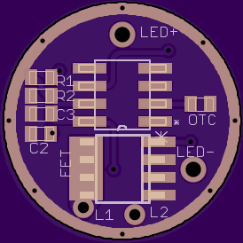
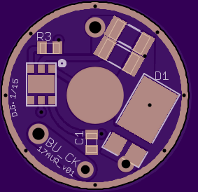
Allright here’s mine. This is based on my running BU_CK so I know the circuit is correct HOWEVER this is a new version I just made with the 13A, the MCU and the voltage divider circuit are both new additions; THIS BOARD IS TECHNICALLY UNTESTED, but again the actual buck components are exactly the same as on my running 22mm driver.
17AVR_v01
Pretty small exposed GND rings but full GND plain’s (this is v01 afterall, expect changes)
This is different that Alex’s circuit by quite a bit, I’m not saying his design is incorrect or doesn’t also work, just that it’s different and I don’t understand how his works (or maybe I’m just seeing the traces on the render incorrectly)
L1 and L2 are the pads for the external toroidal indictor that mounts above (like most commercially available buck driver’s we can buy) this makes for a tall driver but only 17mm Ø.
What's different is that Wight has the inductor on the positive side instead of the negative side, as shown in the datasheet. I'm not sure if it makes any difference which side it is on (either way, the same amount of current should be flowing through the inductor).
Yep, I was just coming here to post I had realized that now. Hey it was late! Plus I didnt know you could do that so it just didnt hit me, when I looked at it today I saw only the inductor was different and figured it much have been ok to do that, it is wight afterall lol.